Visual servo switching control method and system

A visual servo and control method technology, applied in the direction of program control manipulators, manufacturing tools, manipulators, etc., can solve the problems of poor system stability and anti-interference performance, inconvenient use, unstable saturation, etc.

Active Publication Date: 2020-07-03
HARBIN INST OF TECH
View PDF4 Cites 18 Cited by
  • Summary
  • Abstract
  • Description
  • Claims
  • Application Information

AI Technical Summary

Problems solved by technology

[0003] Image position-based visual servoing is suitable for large-scale visual tracking and can be subdivided into control based on joint space and control based on Cartesian space. The former requires trajectory transformation and is inconvenient to use when both position and contact force need to be controlled. ;The latter requires kinematics positive solution in each control cycle, the maximum sampling frequency is lower under the same calculation performance, and the system stability and anti-interference performance are also poor
[0004] Visual servoing based on image features is suitable for small-scale precise positioning, but involves matrix inversion. Under the nonlinear mapping between image feature parameters and operating space variables, the robot may appear in a singular configuration, which will cause instability or control effects. saturation, so that the robot exceeds the motion limits of the joints

Method used


Image

  • Visual servo switching control method and system
  • Visual servo switching control method and system
  • Visual servo switching control method and system

Examples


Embodiment

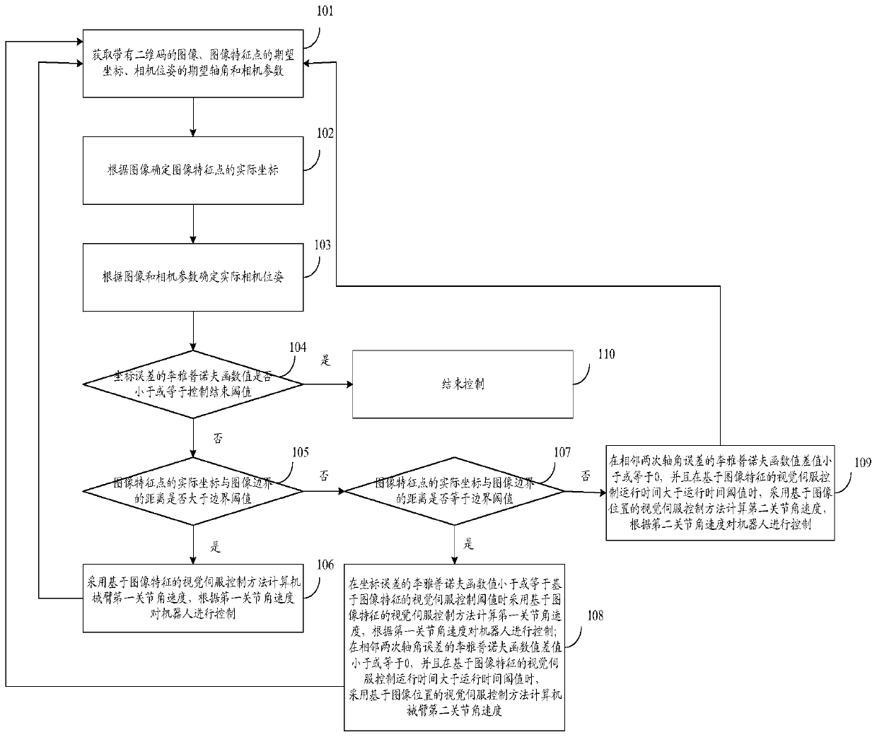
[0087] figure 1 It is a flow chart of the visual servo switching control method in the embodiment of the present invention, such as figure 1 As shown, a visual servo switching control method, including:

[0088] Step 101: Obtain an image with a two-dimensional code, expected coordinates of image feature points, expected axis angle of camera pose, and camera parameters. The image feature points are the corner points of the two-dimensional code.

[0089] Step 102: Determine the actual coordinates of the image feature points according to the image.

[0090] Step 103: Determine the actual camera pose according to the image and camera parameters.

[0091] Step 104: Judging whether the Lyapunov function value of the coordinate error is less than or equal to the control end threshold, and obtaining a first judging result. If the first judgment result is yes, execute step 110; if the first judgment result is no, execute step 105. The coordinate error is the error between the actu...


PUM


Abstract

The invention discloses a visual servo switching control method and system. The method comprises the following steps: determining actual coordinates and actual camera poses of image feature points with two-dimensional codes; if a distance between the actual coordinates of the image feature points and an image boundary is greater than a boundary threshold value, adopting the visual servo control method based on image features to calculate first joint angular velocity of a mechanical arm, and controlling a robot according to the first joint angular velocity; judging whether the distance betweenthe actual coordinates of the image feature points and the image boundary is equal to the boundary threshold value or not, distinguishing and calculating the joint angular velocity; and adopting the visual servo control method based on the image positions to calculate second joint angular velocity if a difference value of Lyapunov function values of adjacent twice axle angle errors is smaller thanor equal to 0, and operation time of the visual servo control based on the image features is greater than an operation time threshold value. The method and the system disclosed by the invention havethe advantages of being capable of strengthening stability of a robot control system, and improving the visual servo effect.

Description

technical field [0001] The invention relates to the technical field of robot visual servo control, in particular to a visual servo switching control method and system. Background technique [0002] At present, all kinds of robots and mechanical arms are widely used in industrial automation, and the visual servo control technology of robots plays a key role. However, the choice of visual servoing control method is a difficult point. Commonly used visual servoing control methods can be divided into visual servoing based on image position and visual servoing based on image features. [0003] Image position-based visual servoing is suitable for large-scale visual tracking, and can be subdivided into control based on joint space and control based on Cartesian space. The former requires trajectory transformation and is inconvenient to use when both position and contact force need to be controlled. ; The latter requires kinematics positive solution in each control cycle, and the m...

Claims


Application Information

Patent Timeline
Patent Type & Authority Applications(China)
IPC IPC(8): B25J9/16
CPCB25J9/1687B25J9/1697
Inventor 高会军刘晨璐姜易木林伟阳佟明斯
Owner HARBIN INST OF TECH
Why Eureka
Try Eureka