
Storage tank device

A technology of equipment and storage tanks, which is applied in the field of liquid storage equipment and can solve problems such as large energy consumption

Pending Publication Date: 2020-07-03
BEIJING TUS CLEAN ENERGY TECH CO LTD
View PDF0 Cites 4 Cited by
  • Summary
  • Abstract
  • Description
  • Claims
  • Application Information

AI Technical Summary

Problems solved by technology

In the process of heating waste oil containing water impurities, electric energy and thermal energy are needed, so the energy consumption is very large.

Method used


Image

  • Storage tank device
  • Storage tank device
  • Storage tank device

Examples


Embodiment Construction

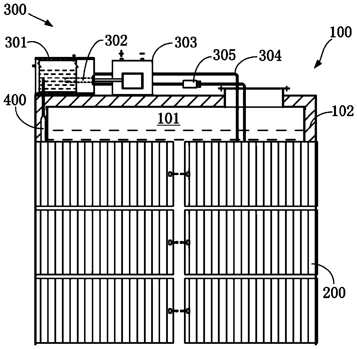
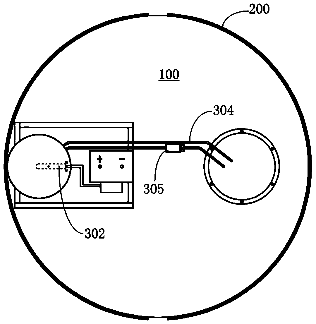
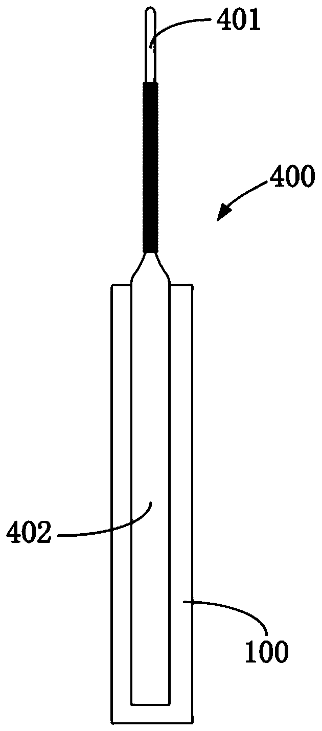
[0036] Hereinafter, some specific embodiments of the present invention will be described in detail by way of illustration and not limitation with reference to the accompanying drawings. The same reference numerals in the drawings designate the same or similar parts or parts. Those skilled in the art will appreciate that the drawings are not necessarily drawn to scale. figure 1 is a partially cutaway schematic front view of the storage tank equipment; figure 2 yes figure 1 a schematic top view of image 3 is a schematic front view of the metal heat pipe.

[0037] see figure 1 and figure 2 , this embodiment provides a storage tank device, including: a tank body 100 , a solar panel 200 and an electric heating device 300 . A storage space 101 is formed in the tank body 100, and the tank body 100 can conduct heat; the back plate of the solar cell panel 200 is connected to the outer wall of the tank body 100, so as to transfer the heat of the solar cell panel 200 to the stor...


PUM


Abstract

The invention provides a storage tank device, and relates to a liquid storage device. The storage tank device comprises a tank body, solar panels and an electric heating device, wherein a containing space is formed in the tank body, the tank body can conduct heat, back plates of the solar panels are connected with the outer side wall of the tank body so that the heat of the solar panels can be transmitted to the containing space through the tank body, the electric heating device is connected with the solar panels, and one part of the electric heating device is disposed in the containing spaceof the tank body to heat the containing space. Under the cooperation of the solar panels, water-impurity-containing gutter oil in the storage tank device is sufficiently heated through clean energy, and energy consumption is reduced; the temperature coefficient effect of photovoltaic panels is weakened, and the power output of the solar panels is improved; and the size of the storage tank device equipped with the solar panels is reduced as much as possible.

Description

technical field [0001] The invention relates to a liquid storage device, in particular to a storage tank device. Background technique [0002] As one of the crude oils required for biodiesel preparation, the water content in waste oil is generally about 3%, and the oil has poor fluidity at room temperature. If there is no external heat source to increase the oil temperature of waste oil to improve its fluidity, water impurities Settling is difficult, and it will enter the biodiesel preparation reaction system with waste oil, which will bring a series of problems. For this reason, the current method of removing impurities generally adopts enzymatic reaction, and because lipase is relatively expensive, lipase needs to be recycled. After the reaction, it needs to be centrifuged to obtain an oil phase and a water phase, and the water phase is intercepted by a ceramic membrane to remove the lipase Retain, let the reaction excess methanol, the water and glycerin by-products produ...

Claims


Application Information

Patent Timeline
Patent Type & Authority Applications(China)
IPC IPC(8): B65D88/74
CPCB65D88/744
Inventor 刘奎朱罗乐焦记稳
Owner BEIJING TUS CLEAN ENERGY TECH CO LTD
Learn More