Al technical title is built by PatSnap Al team. It summarizes the technical point description of the patent document.
A technology of hydraulic device and wheel chain, applied in the direction of transmission device, friction transmission device, transmission device parts, etc., can solve the problems of easy change of upper and lower rail clearance, inability to perform online real-time adjustment, etc., to increase heat transfer coefficient and enhance heat dissipation. effect of effect
Active Publication Date: 2022-01-21
江苏省机械研究设计院有限责任公司
View PDF7 Cites 0 Cited by
Summary
Abstract
Description
Claims
Application Information
AI Technical Summary
This helps you quickly interpret patents by identifying the three key elements:
Problems solved by technology
Method used
Benefits of technology
Problems solved by technology
[0007] Aiming at the problems in the prior art that the tensioning pressure is fixed, when the tensioning condition of the sprocket chain plate changes, online real-time adjustment cannot be performed, and the gap between the upper and lower rails is easy to change, the present invention provides a thermal transmission sprocket chain plate Tension hydraulic device
Method used
Image
Click on the blue label to locate the original text in one second.
Reading with bidirectional positioning of images and text.
Examples
Embodiment Construction
[0034] The present invention will be further described below in conjunction with specific embodiments.
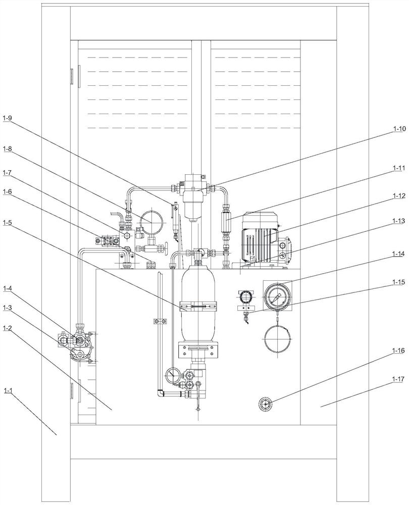
[0035] Such as figure 1 and figure 2 As shown, the present invention includes a protective outer frame 1-1, an oil tank 1-2, an automatic temperature control system, a control system, a hydraulic power system, a hydraulic control system, and an oil cylinder assembly. The protective outer frame 1-1 is a rectangular steel pipe and a steel plate weldment, and doors are installed on the left, right, front, rear, and four sides, and vent holes are opened on the doors to protect the body; the fuel tank 1-2 is arranged in the protective outer frame 1-1, The automatic temperature control system, hydraulic power system, and hydraulic control system are arranged around the oil tank 1-2 and inside the protective outer frame 1-1; the control system is arranged in the electric control collection cabinet 1-17, and the electric control collection cabinet 1-17 is set In the protective o...
PUM
Abstract
The invention discloses a hydraulic device for tensioning a chain plate of a transmission heat chain wheel, comprising a fuel tank, an oil cylinder, a motor pump, a pressure holding chamber, a hydraulic control module, an accumulator, a pressure relay, a pressure relay for an oil cylinder, a control system, and a hydraulic control module Including the second solenoid valve, the motor pump is connected to the oil tank, the oil outlet of the motor pump, the hydraulic control module, the pressure maintaining chamber, and the oil inlet of the oil cylinder are connected in sequence, and the oil outlet of the oil cylinder is connected to the oil tank through the hydraulic control module; the accumulator enters the oil The port is connected to the pressure maintaining chamber, and the oil discharge port is connected to the oil tank; when the oil pressure reaches P2, the pressure relay sends a signal to the control system to start the motor pump; when the oil pressure reaches P1, the pressure relay sends a signal to the control system to shut down the motor pump; When the hydraulic pressure reaches P4, the pressure relay sends a signal to the control system to close the second solenoid valve; when the oil pressure in the oil cylinder reaches P3, the oil cylinder pressure relay sends a signal to the control system to start the motor pump, wherein, P3>P1>P2>P4. The invention provides stable hydraulic power for the oil cylinder.
Description
technical field [0001] The invention relates to a hydraulic device, in particular to a tensioning hydraulic device for a hot sprocket chain plate transmission mechanism with a certain temperature. Background technique [0002] The temperature of the sprocket chain itself and the surrounding environment is relatively high. The tension of some sprocket drive systems and the adjustment of the gap between the upper and lower rails are the key links to ensure the quality of finished products. In the past, the tensioning of the sprocket chain plate transmission system used the weight tensioning method or the simple tensioning method. The weight tensioning method is adopted, the tension force is fixed, and the value of the counterweight is calculated and determined according to the normal heavy-duty working condition. When the tensioning condition of the sprocket and chain plate changes, online real-time adjustment cannot be performed, and the upper and lower rails Clearance is ea...
Claims
Application Information
Patent Timeline
Application Date:The date an application was filed.
Publication Date:The date a patent or application was officially published.
First Publication Date:The earliest publication date of a patent with the same application number.
Issue Date:Publication date of the patent grant document.
PCT Entry Date:The Entry date of PCT National Phase.
Estimated Expiry Date:The statutory expiry date of a patent right according to the Patent Law, and it is the longest term of protection that the patent right can achieve without the termination of the patent right due to other reasons(Term extension factor has been taken into account ).
Invalid Date:Actual expiry date is based on effective date or publication date of legal transaction data of invalid patent.