Three-phase dual-active-bridge direct-current converter control system and control method

A technology of DC converter and dual active bridge, which is applied in the direction of control/regulation system, conversion of DC power input to DC power output, instruments, etc. It can solve the problems of slow response and achieve output voltage deviation, clear physical meaning, Effects that are easy to analyze

Active Publication Date: 2020-07-03
HEFEI KEWELL POWER SYST CO LTD
View PDF5 Cites 6 Cited by
  • Summary
  • Abstract
  • Description
  • Claims
  • Application Information

AI Technical Summary

Problems solved by technology

[0007] The technical problem to be solved by the present invention is how to solve the problem that the response of the single closed-loop proportional-integral regulator to the step change of the output load is slower than that of the reference voltage step change

Method used


Image

  • Three-phase dual-active-bridge direct-current converter control system and control method
  • Three-phase dual-active-bridge direct-current converter control system and control method
  • Three-phase dual-active-bridge direct-current converter control system and control method

Examples


Embodiment 1

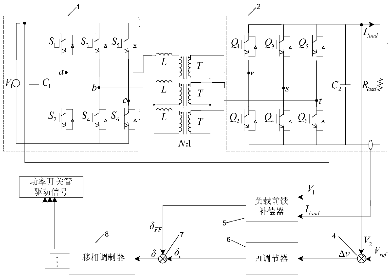
[0053] like figure 1 As shown, a three-phase dual active bridge DC converter control system includes a front-stage three-phase H-bridge inverter 1, a rear-stage three-phase H-bridge rectifier 2, three single-phase high-frequency transformers T, three A phase-shifting inductor L, the windings of the three single-phase high-frequency transformers T are connected to the front-stage three-phase H-bridge inverter 1 and the rear-stage three-phase H-bridge rectifier 2 according to a Y-Y-shaped connection mode, so that The three phase-shifting inductors L described above are respectively connected in series between the pre-stage three-phase H-bridge inverter 1 and the single-phase high-frequency transformer T; the three-phase dual active bridge DC converter control system also includes a power switch Tube drive system and load feed-forward compensation system.

[0054] The power switch tube drive system includes a first subtractor 4, a PI regulator 6, a first adder 7, a phase shift m...

Embodiment 2

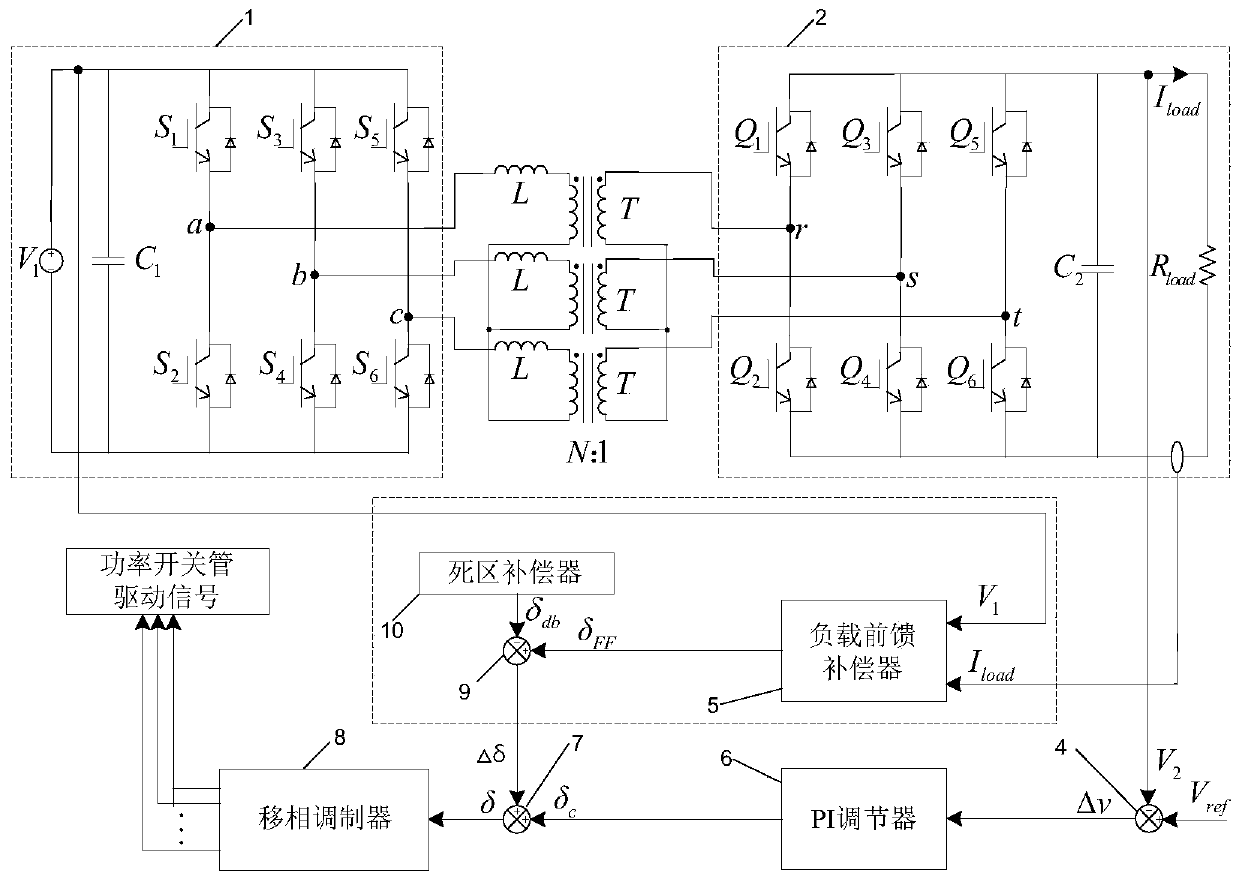
[0070] like figure 2 As shown, the difference between the three-phase dual active bridge DC converter control system of this embodiment and the first embodiment is that the load feed-forward compensation system also includes a second subtractor 9 and a dead zone compensator 10; The dead zone compensator 10 generates a phase shift angle command value δ for dead zone compensation db ; The second subtractor 9 will feed-forward compensation phase shift angle command value δ FF Phase shift angle command value δ with dead zone compensation db make difference to get δ FF -δ db , put δ FF -δ db Send into the first adder 7 and need to adjust the phase shift angle δ c Add to get the effective phase shift angle δ, that is, δ=δ c +δ FF -δ db .

[0071] The dead zone compensator 10 generates a phase shift angle command value δ for dead zone compensation db , is the command value of phase shift angle δ db The formula for calculating:

[0072]

[0073] Among them, δ s is th...

Embodiment 3

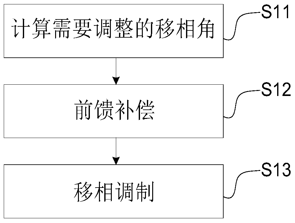
[0075] like image 3 As shown, a three-phase dual active bridge DC converter control method in this embodiment is applied to the control system described in Embodiment 1, and the control method includes the following steps: S11: Calculate the phase shift angle that needs to be adjusted ; S12: feedforward compensation, S13: phase shift modulation.

[0076] The control method of a three-phase dual active bridge DC converter in this embodiment has a clear physical meaning, is easy to analyze, and can well realize rapid stability and precise adjustment of the output voltage.

[0077] S11: Calculate the phase shift angle that needs to be adjusted, specifically:

[0078] The first subtractor 4 collects the system output DC voltage V 2 with a given output voltage reference V ref Make a difference to get the output voltage error signal Δv, and input the output voltage error signal Δv to the PI regulator to get the phase shift angle δ that needs to be adjusted c .

[0079] S12: Fe...


PUM


Abstract

The invention discloses a three-phase dual-active-bridge direct-current converter control system. The invention belongs to the technical field of power electronics, the problem that a single closed-loop proportional-integral regulator is slow in response to step change of an output load is solved. The system comprises a front-stage three-phase H-bridge inverter, a rear-stage three-phase H-bridge rectifier, three single-phase high-frequency transformers and three phase-shifting inductors, windings of the three single-phase high-frequency transformers are connected with the preceding-stage three-phase H-bridge inverter and the backward-stage three-phase H-bridge rectifier in a Y-Y-shaped connection mode, and the three phase-shifting inductors are connected between the preceding-stage three-phase H-bridge inverter and the single-phase high-frequency transformers in series; the system further comprises a power switch tube driving system and a load feedforward compensation system. The output voltage deviation of the converter is minimized when the reference voltage and the output load are subjected to step change; the control method can realize rapid, stable and accurate adjustment of the output voltage; after dead zone compensation control is added, the power transmission precision of the converter under phase shift modulation is improved.

Description

technical field [0001] The invention belongs to the technical field of power electronics, and relates to a control system and a control method for a three-phase dual active bridge DC converter. Background technique [0002] Three-phase dual active bridge DC converters are widely used in high-power and high-voltage power because of their excellent characteristics such as input and output isolation, suitable for high-power applications, high reliability, ZVS soft switching, high power density, and bidirectional power flow. In the system, the dynamic performance of the three-phase dual active bridge DC converter is a research hotspot in this field. When the load or reference voltage is disturbed, the fast dynamic response can not only reduce the transient output voltage deviation, but also make the output DC bus capacitance smaller, which reduces the size and weight and improves the power density. [0003] With regard to improving the dynamic performance of the three-phase dua...

Claims


Application Information

Patent Timeline
IPC IPC(8): H02M3/335
CPCH02M3/33507H02M3/3353H02M1/0016
Inventor 唐德平
Owner HEFEI KEWELL POWER SYST CO LTD
Why Eureka
Try Eureka