
Machining device for deep-hole high-precision sealing surface

A processing device and sealing surface technology, which is applied in the direction of grinding device, metal processing equipment, manufacturing tools, etc., can solve the unqualified coloring of the valve seat of the lubricating oil accessory, the unqualified verticality and flatness of the bottom surface of the lubricating oil accessory valve and the hole, Problems such as processing and measurement difficulties

Inactive Publication Date: 2020-07-07
CHINA HANGFA GUIZHOU LIYANG AVIATION POWER CO LTD
View PDF6 Cites 1 Cited by
  • Summary
  • Abstract
  • Description
  • Claims
  • Application Information

AI Technical Summary

Problems solved by technology

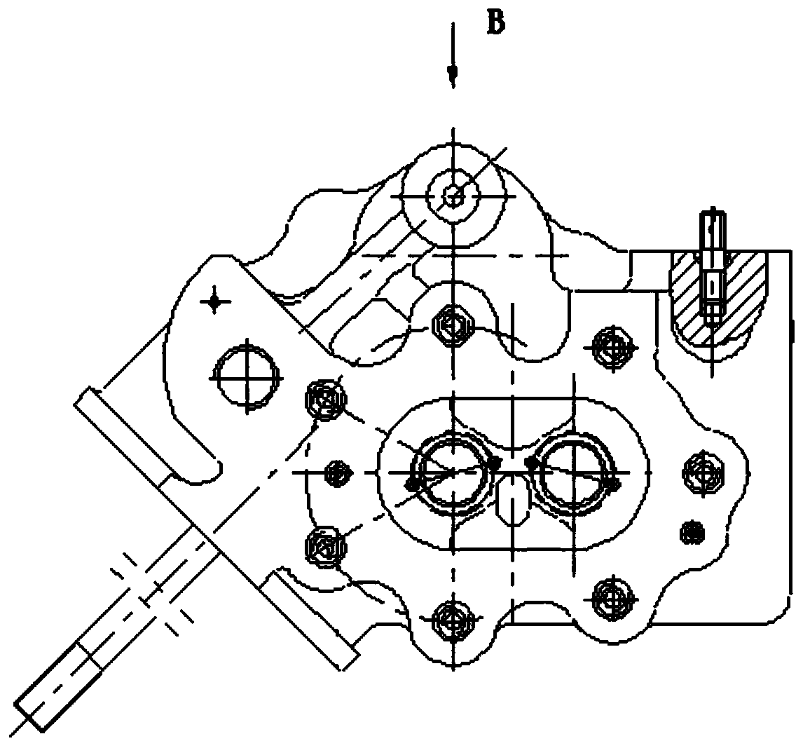
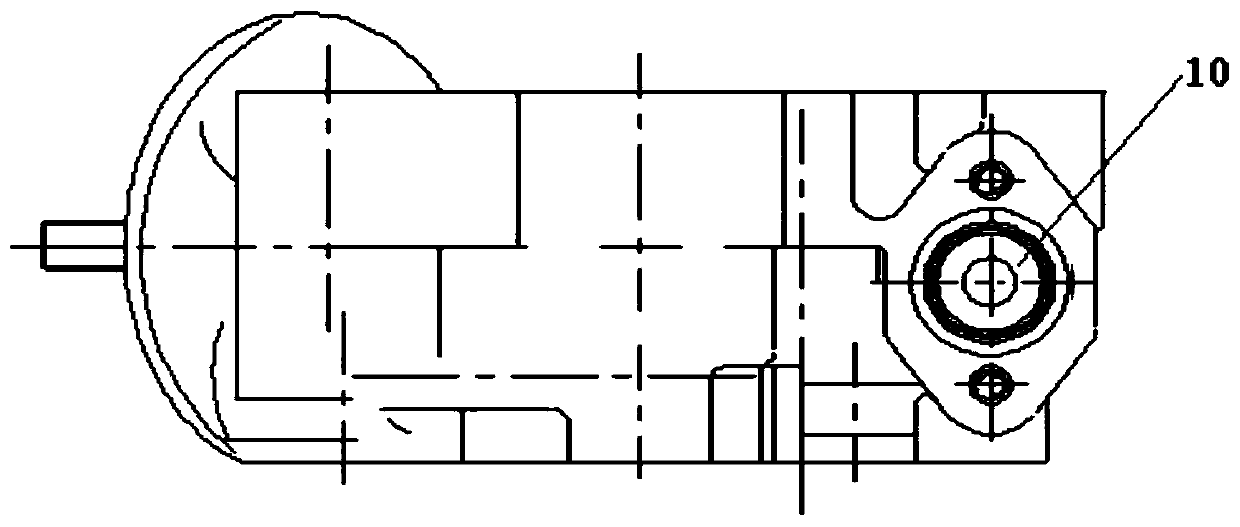
[0002] The coloring of the oil accessory valve seat of a certain type of machine is unqualified. During the assembly process, it is found that the verticality and flatness between the bottom surface of the oil accessory valve and the hole are unqualified, such as Figure 4-5 As shown, the bottom surface of the valve seat of this part is in the process of processing, because it cooperates with another part to seal the oil, so the plane coloring checks the flatness, and at the same time it needs to be perpendicular to the center line of the hole, which is very difficult to process and measure. Therefore, it is urgently needed Provide a machining tool specially designed for machining such sealing surfaces

Method used


Image

  • Machining device for deep-hole high-precision sealing surface
  • Machining device for deep-hole high-precision sealing surface
  • Machining device for deep-hole high-precision sealing surface

Examples


Embodiment Construction

[0019] The technical solution of the present invention is further described below, but the scope of protection is not limited to the description.

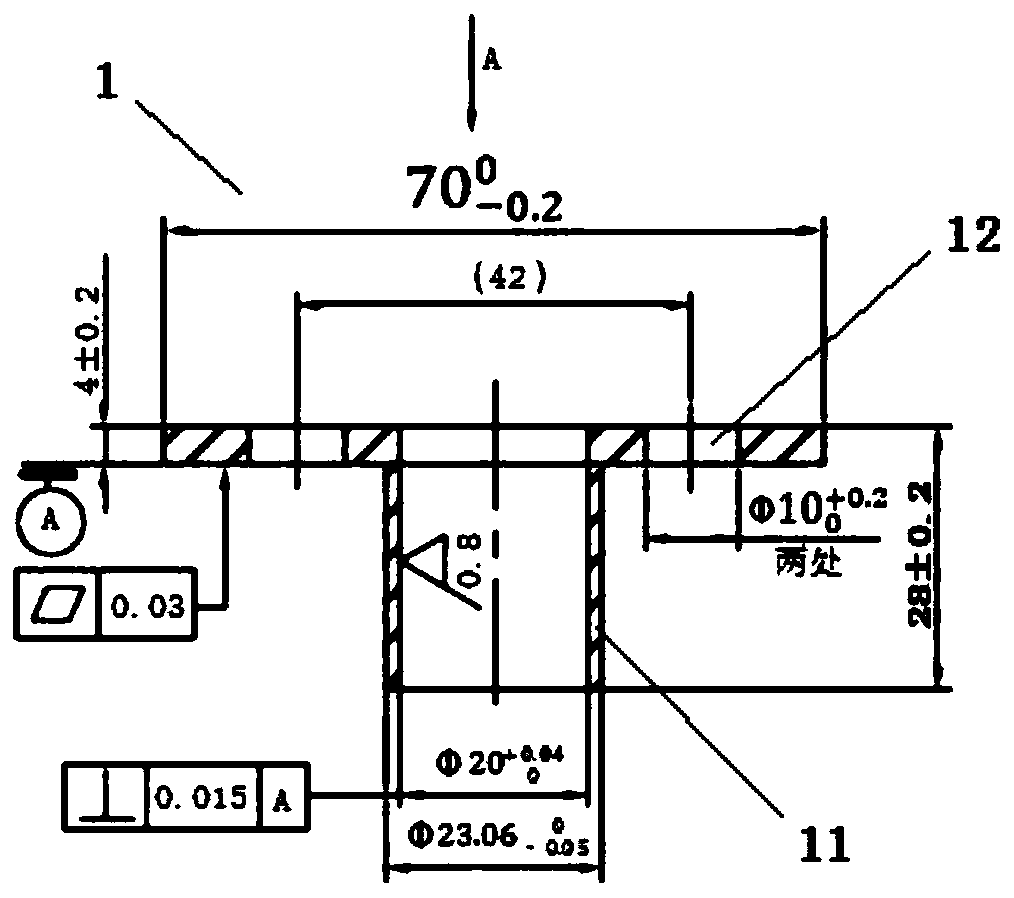
[0020] like Figure 1-5 As shown, a processing device for deep-hole high-precision sealing surface includes a sleeve 1 and a pin 2, wherein the sleeve 1 is T-shaped, and the middle part of the bottom surface is provided with an outwardly protruding cylinder 11. The outer diameter of the cylinder 11 is adapted to the inner diameter of the deep hole to be processed. There are two mounting holes 12 symmetrical to the cylinder 11 on the bottom surface. When working, the sleeve 11 can be fixed to the hole to be processed through the mounting holes 12. On deep hole parts;

[0021] The diameter of the pin rod 2 is adapted to the inner diameter of the cylinder 11. The upper end of the pin rod is provided with knurling 21 along the outer wall, and the lower end is provided with a boss. The size of the table surface 22 of the boss is the sa...


PUM

PropertyMeasurementUnit
Widthaaaaaaaaaa
Thicknessaaaaaaaaaa
Lengthaaaaaaaaaa

Abstract

The invention discloses a machining device for a deep-hole high-precision sealing surface. The machining device of the deep-hole high-precision sealing surface comprises a sleeve and a pin rod, wherein the sleeve is T-shaped; a cylinder which protrudes outwards is formed in the centre of the bottom surface of the sleeve; the size of the outside diameter of the cylinder is adapted to that of the inside diameter of a deep hole to be machined; two mounting holes which are symmetrical with the cylinder are formed in the bottom surface; the size of the diameter of the pin rod is adapted to that ofthe inside diameter of the cylinder; knurls are formed along the outer wall of the upper end of the pin rod; a lug boss is formed at the lower end of the pin rod; the size of the countertop of the lugboss is adapted to that of a sealing surface with the deep hole to be machined; the countertop of the lug boss is a grinding surface; after the sealing surface is machined by using the machining device, the hole machining deformation of a part is greatly improved; the part yield is improved; the machining preparation time is greatly shortened, and meanwhile, the size precision is greatly improved; the technical requirement of 100 percent coloring of an end surface of the part can be met; the machining device can be popularized and applied to the machining of parts of the same type of other machine models; and the machining performance of a casing is improved.

Description

technical field [0001] The invention belongs to the processing and manufacturing technology of lubricating oil accessory parts of aero-engines, and in particular relates to a processing device for deep-hole high-precision sealing surfaces. Background technique [0002] The coloring of the oil accessory valve seat of a certain type of machine is unqualified. During the assembly process, it is found that the verticality and flatness between the bottom surface of the oil accessory valve and the hole are unqualified, such as Figure 4-5 As shown, the bottom surface of the valve seat of this part is in the process of processing, because it cooperates with another part to seal the oil, so the plane coloring checks the flatness, and at the same time it needs to be perpendicular to the center line of the hole, which is very difficult to process and measure. Therefore, it is urgently needed A machining tool specially designed for machining such sealing surfaces is provided. Contents...

Claims


Application Information

Patent Timeline
IPC IPC(8): B24B37/02B24B37/34
CPCB24B37/02B24B37/34
Inventor 胡鹏刘玉婵林姗高文宝农伟廖美英王伟青余长久
Owner CHINA HANGFA GUIZHOU LIYANG AVIATION POWER CO LTD
Learn More