Double-furnace-core-rod sintering device with stable temperature field and stable flow field

A sintering device and temperature field technology, applied in manufacturing tools, glass manufacturing equipment, etc., can solve the problems of prolonged operation time, high cost, and large consumption of helium gas

Pending Publication Date: 2020-07-07
杭州永通智造科技有限公司
View PDF0 Cites 1 Cited by
  • Summary
  • Abstract
  • Description
  • Claims
  • Application Information

AI Technical Summary

Problems solved by technology

[0004] At present, domestic prefabricated rod manufacturers mostly use single furnace structure sintering equipment for mandrel sintering. The dehydration process and sintering process are completed in the same heating zone. Due to the short dehydration area of ​​single furnace operation, local dehydration is required, and the dehydration time is long. Dehydration and sintering The sintering room needs to wait for the temperature to rise, so the operation time will be prolonged. Taking the operation of a loose body with a length of 1200mm as an example, the total operating time of a single furnace is about 780 minutes, and the dehydration length is 1200mm. The total height of the zone is 2000mm (3 zones in the middle, and auxiliary heating in the upper and lower zones). During the sintering and dehydration operation, helium needs to be introduced all the time. If the time is long, the amount of helium will be large, the cost will be high, and there will be low operating efficiency, large helium consumption, and Unstable temperature, pressure and flow field in the furnace

Method used


Image

  • Double-furnace-core-rod sintering device with stable temperature field and stable flow field
  • Double-furnace-core-rod sintering device with stable temperature field and stable flow field

Examples


Embodiment Construction

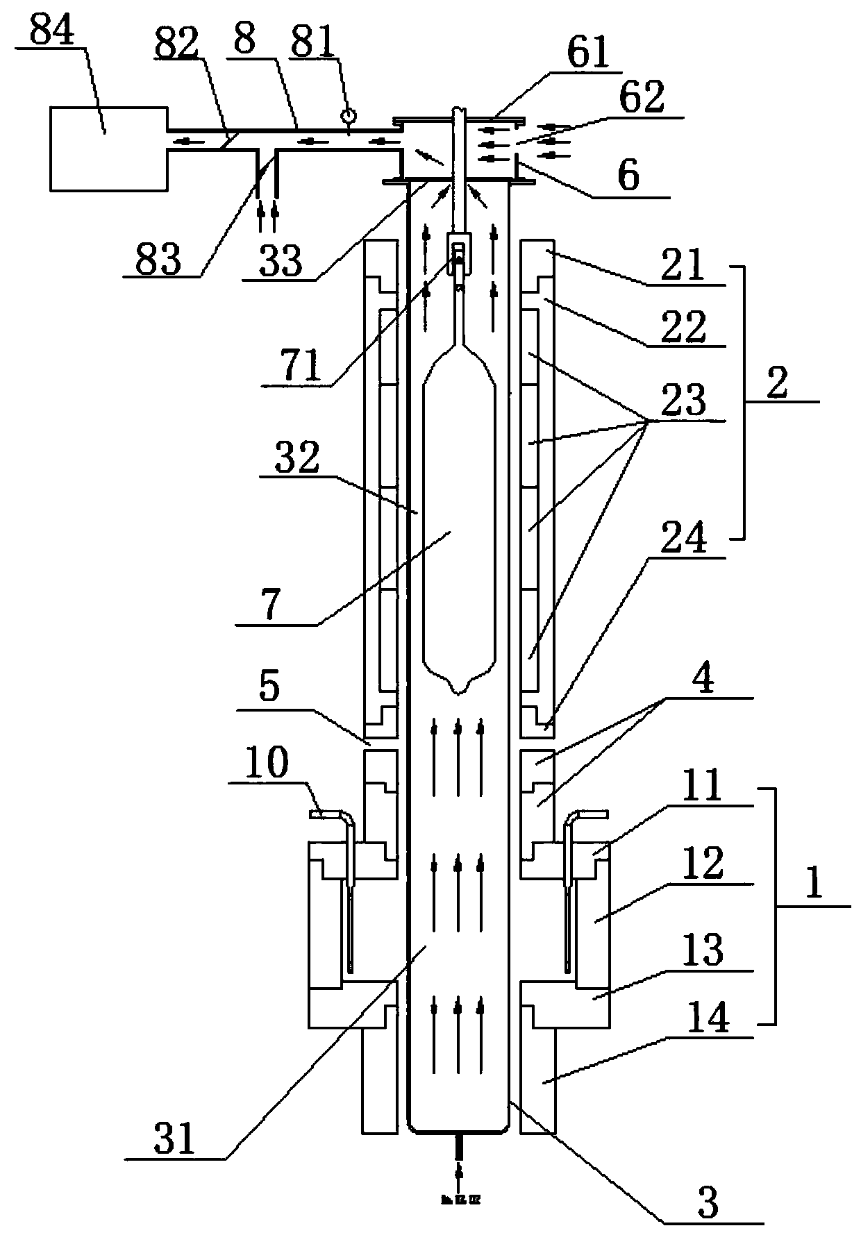
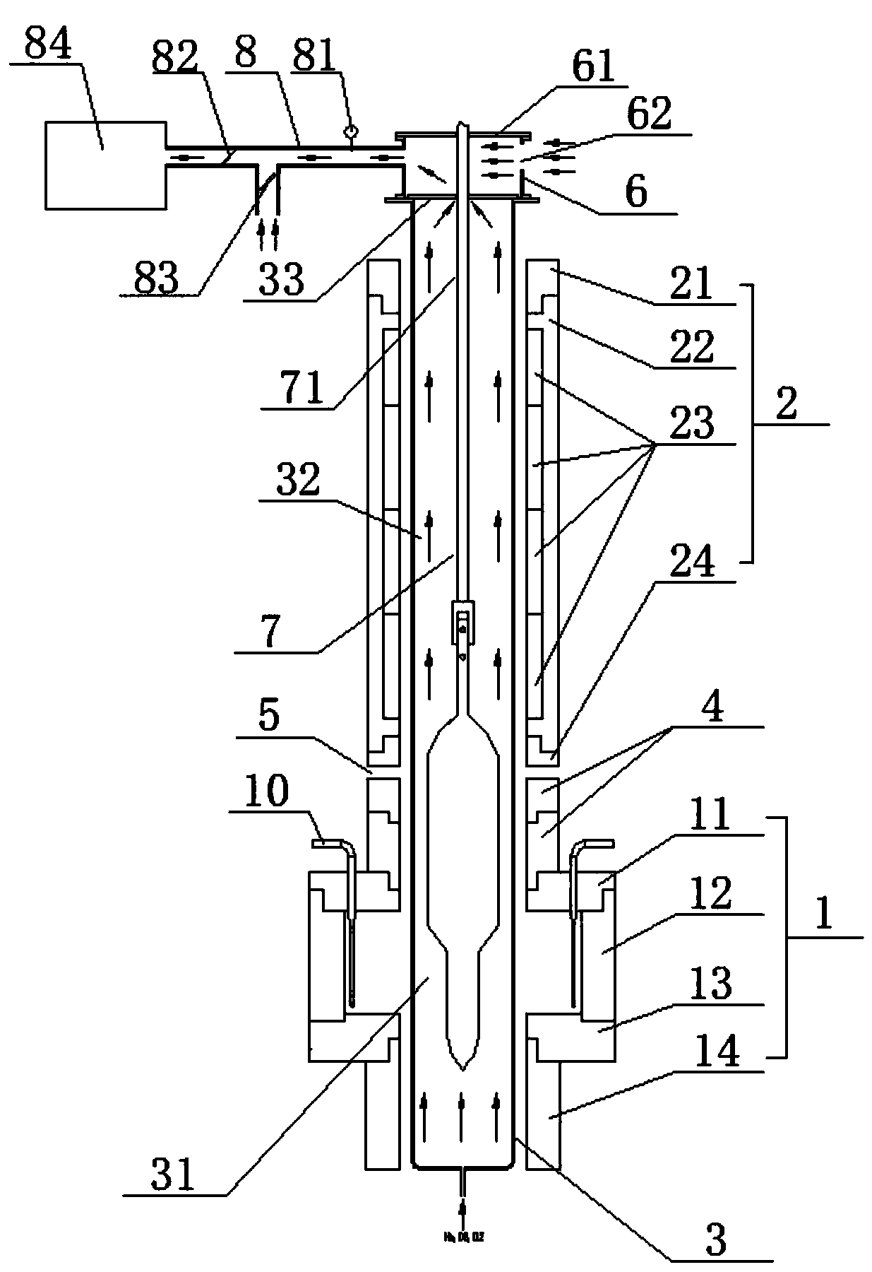
[0021] refer to figure 1 , figure 2 , the present invention is a double-furnace mandrel sintering device with stable temperature field and flow field. Tube 3, process gas helium, oxygen and chlorine enter from the bottom of muffle tube 3, between sintering furnace 1 and dehydration furnace 2 there is an inter-furnace insulation 4 and a temperature balance zone 5, the inside of muffle tube 3 corresponds to sintering furnace 1 The inner area of ​​the dehydration furnace 2 is a sintering zone 31 and a dehydration zone 32 respectively, the top of the muffle tube 1 is provided with a muffle tube cover plate 33, and the air inlet and exhaust waste treatment device includes an exhaust hood with an exhaust hood cover plate 61 and an air inlet 62. Gas hood 6, exhaust pipe 8, exhaust gas treatment device 84, exhaust pipe 8 is provided with fresh air branch with fresh air valve 83, pressure gauge 81 and main air valve 82, exhaust hood cover plate 61 and muffle pipe cover A traction de...


PUM


Abstract

The invention discloses a double-furnace-core-rod sintering device with a stable temperature field and a stable flow field. The device comprises a sintering furnace, a dehydration furnace, an air inlet waste discharge treatment device and a muffle pipe arranged in the sintering furnace and the dehydration furnace in a penetrating mode. An inter-furnace heat preservation piece and a temperature balance area are arranged between the sintering furnace and the dehydration furnace. A sintering area and a dehydration area are arranged in the muffle pipe; a muffle tube cover plate is arranged at thetop of the muffle pipe; and the air inlet and waste discharge treatment device comprises an exhaust hood, an exhaust pipe and a waste gas treatment device. A fresh air branch with a fresh air valve, apressure gauge and a main air valve are arranged on the exhaust pipe, a traction device is arranged on the exhaust hood cover plate and the muffle tube cover plate in the penetrating mode, a loose product is installed at the lower end of the traction device and inserted into the muffle tube to be dehydrated and sintered, and the exhaust hood, the muffle tube, the exhaust pipe and the waste gas treatment device are communicated. The device has the advantages that the temperature in the furnace and the temperature and the pressure in the muffle tube are stable, the sintering dehydration operation time and the production cost are reduced, the overall working efficiency is improved, and a temperature field and a flow field are stable.

Description

【Technical field】 [0001] The invention relates to the technical field of mandrel sintering devices, in particular to the technical field of a double-furnace mandrel sintering device with stable temperature field and flow field. 【Background technique】 [0002] With the development of the optical fiber market, especially in recent years, the price of raw materials has continued to rise, but the price of optical fiber has not risen simultaneously. For optical fiber preform manufacturers, reducing preform manufacturing costs, reducing raw material consumption and improving production efficiency have become become the trend. [0003] The sintering of the mandrel loose body needs to go through two steps of dehydration and sintering. The dehydration and sintering processes need to be carried out at a certain temperature, and chlorine, helium and oxygen are used to react during the process. Due to the residual water molecules in the deposition process of the loose body, the origina...

Claims


Application Information

Patent Timeline
IPC IPC(8): C03B37/014C03B37/018
CPCC03B37/01446C03B37/01853
Inventor 宋大吉徐威章宇航
Owner 杭州永通智造科技有限公司
Why Eureka
Try Eureka