
Light guide and condensation structure for surface-mounted LED

A technology of light-emitting diode and light-concentrating structure, applied in the field of light-concentrating structure and light guide, can solve the problems of difficulty in independent application of equipment, inability to concentrate, and large design area.

Inactive Publication Date: 2020-07-07
上海和宗焊接设备制造有限公司
View PDF3 Cites 0 Cited by
  • Summary
  • Abstract
  • Description
  • Claims
  • Application Information

AI Technical Summary

Problems solved by technology

One is the self-contained light guide column, and the light can be focused in a certain area, but due to the long soldering pins of the components, SMT manual cutting and soldering are required during installation, which brings disadvantages to mass production man-hours and universal design PCB design; One is a patch-shaped light-emitting diode. Although it can be quickly welded and applied in a large area, it cannot be concentrated in a certain area for display due to the divergence of the emitted light source, and it is difficult to be independently applied to the device.
[0004] Because the existing two forms of LED light-emitting diodes have their own disadvantages in the use process, the LED with its own light guide column has the problem of manual cutting and welding when installing, and the patch-shaped LED also has light source divergence, which cannot be concentrated on a certain one. area display problem
Therefore, the LED in the prior art has the disadvantages of large design area and slow processing and production efficiency.

Method used


Image

  • Light guide and condensation structure for surface-mounted LED
  • Light guide and condensation structure for surface-mounted LED
  • Light guide and condensation structure for surface-mounted LED

Examples


Embodiment 1

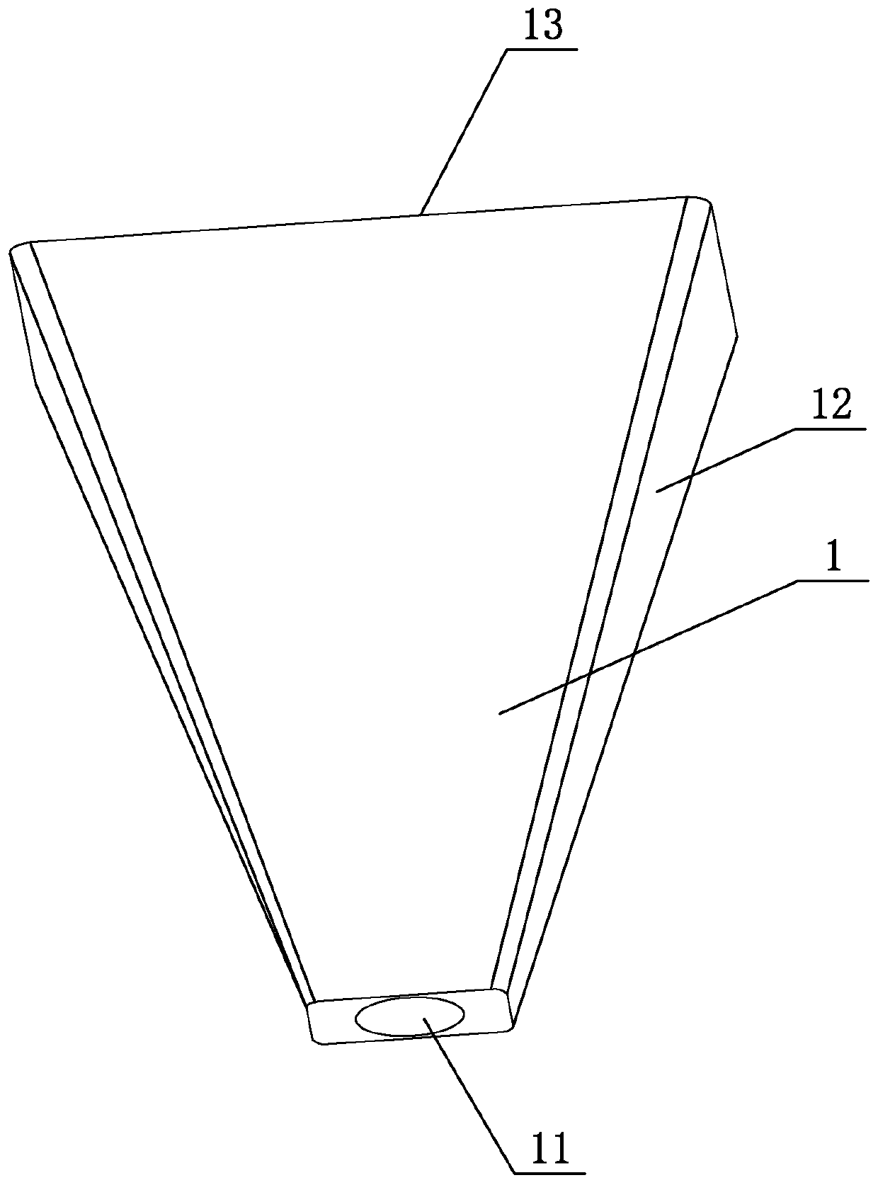
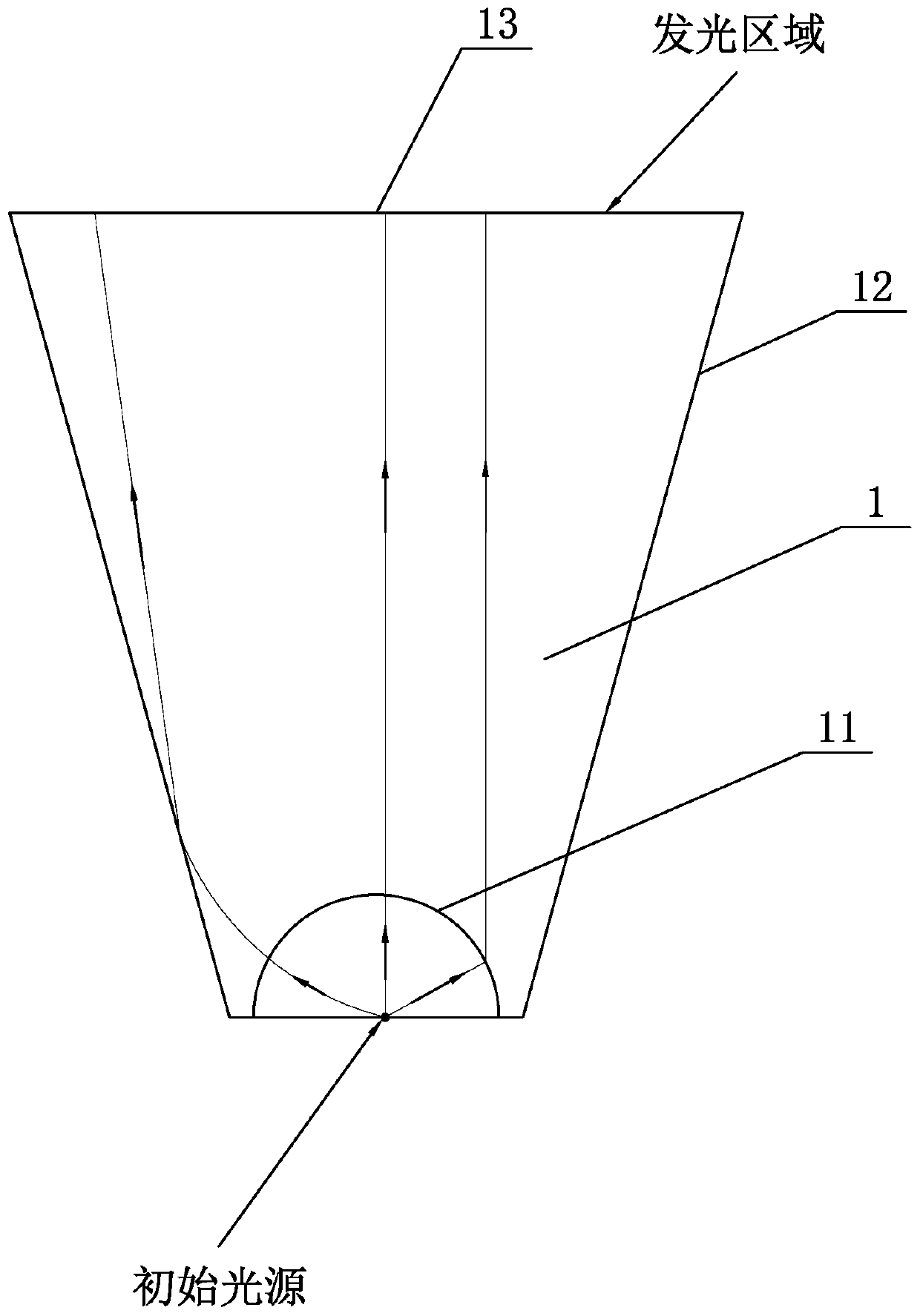
[0028] A light-guiding and light-condensing structure for patch LED light-emitting diodes, refer to figure 1 It can be seen that the shape of the main body is composed of the main body 1, the outer shape of the main body 1 is in the shape of a square truss, the interior of the main body 1 is a solid structure, and the main body 1 is made of transparent PC material by injection molding, forming a fully transparent structure. The outer surface around the body 1 is a total reflection surface 12 , and the bottom surface of the body 1 is a light-emitting surface 13 . Wherein, the total reflection surface 12 is a smooth surface, and its surface roughness is below 0.8.

[0029] The top surface of the quadrangular pedestal is provided with a concave scattering spherical surface 11, and the scattering spherical surface 11 is a concave hemispherical surface. The position of the center of the sphere 11.

[0030] When in use: the initial light source is made of 3258 SMD LED lamp beads, ...

Embodiment 2

[0032] A light-guiding and light-condensing structure for patch LED light-emitting diodes, refer to figure 1 It can be seen that the shape of the main body is composed of the main body 1, the outer shape of the main body 1 is a pentagonal truss shape, the interior of the main body 1 is a solid structure, and the main body 1 is made of transparent PC material by injection molding, forming a fully transparent structure. The outer surface around the body 1 is a total reflection surface 12 , and the bottom surface of the body 1 is a light-emitting surface 13 . Wherein, the total reflection surface 12 is a smooth surface, and its surface roughness is below 0.8.

[0033] The top surface of the five-prism platform is provided with a concave scattering spherical surface 11, and the scattering spherical surface 11 is a concave hemispherical surface. The position of the center of the sphere 11.

[0034] When in use: the initial light source is made of 3258 SMD LED lamp beads, its lumi...

Embodiment 3

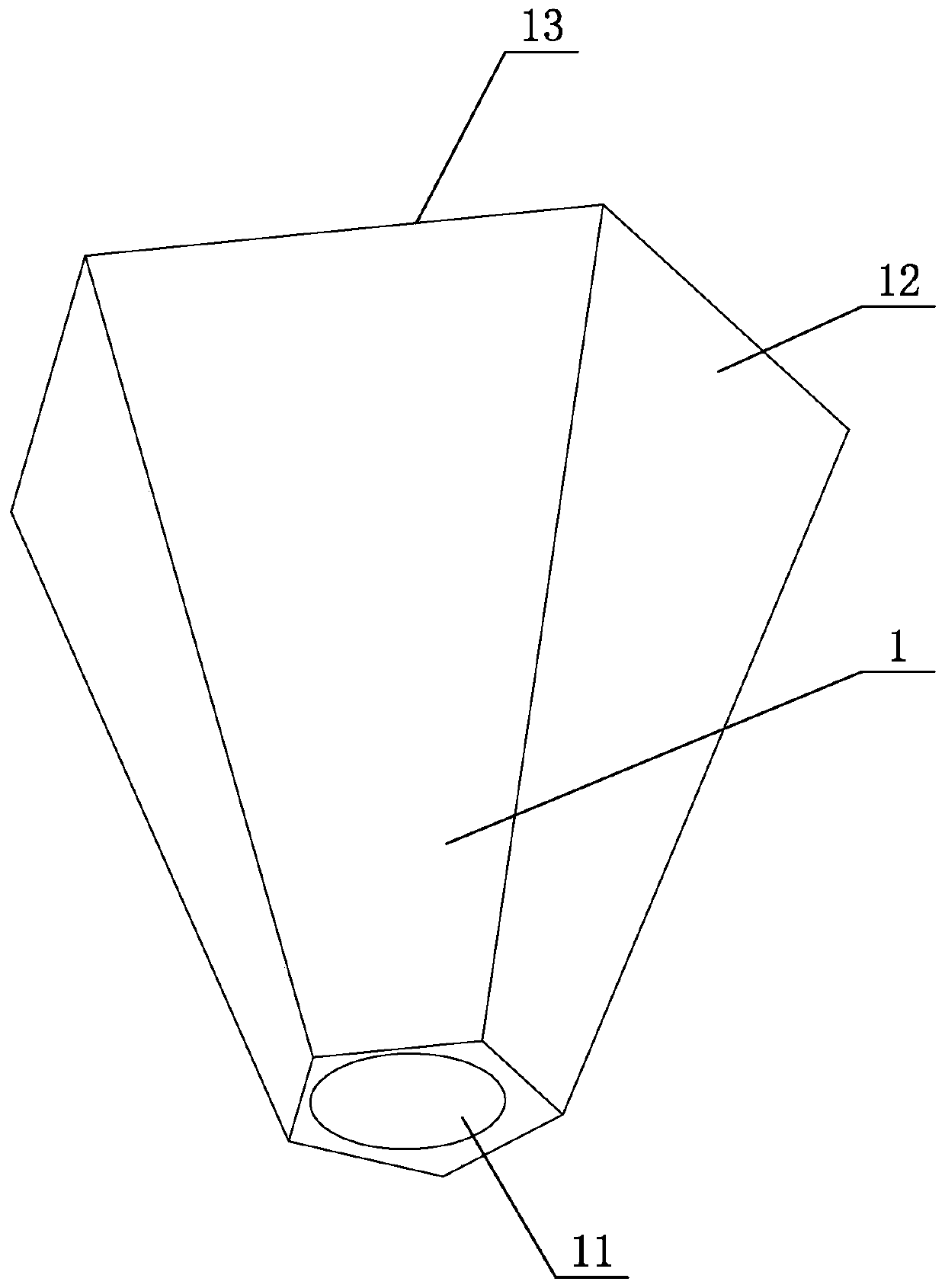
[0036] A light-guiding and light-condensing structure for patch LED light-emitting diodes, refer to figure 1 It can be seen that the shape of the main body is composed of the body 1, the shape of the body 1 is in the shape of a hexagonal truss, the interior of the body 1 is a solid structure, and the body 1 is made of transparent PC material by injection molding, forming a fully transparent structure. The outer surface around the body 1 is a total reflection surface 12 , and the bottom surface of the body 1 is a light-emitting surface 13 . Wherein, the total reflection surface 12 is a smooth surface, and its surface roughness is below 0.8.

[0037] The top surface of the hexagonal platform is provided with a concave scattering spherical surface 11, and the scattering spherical surface 11 is a concave hemispherical surface. The position of the center of the sphere 11.

[0038] When in use: the initial light source is made of 3258 SMD LED lamp beads, its luminous points are co...


PUM


Abstract

The invention belongs to the technical field of LED light source application, discloses a light guide and condensation structure for a surface-mounted LED and aims to solve the problems of large design area and low machining and production efficiency. The light guide and condensation structure comprises a body; the body is in the shape of a prismoid; a concave scattering spherical surface is formed in the top surface of the prismoid; the scattering spherical surface is a semispherical surface; the interior of the body is of a solid structure and is fully transparent; the outer surface of the peripheral side of the body is a total-reflection surface; and the bottom surface of the body is a light-emitting surface. According to the technical schemes, emitted light of the surface-mounted LED is focused, and therefore, the surface-mounted LED can give full play to the characteristics of small area, convenience in flexible design, rapid production and machining and the like in an actual production and use process.

Description

technical field [0001] The invention relates to the technical field of LED light source application, more specifically, it relates to a light guiding and concentrating structure for patch LED light-emitting diodes. Background technique [0002] LED, Chinese name: light-emitting diode, is a solid-state semiconductor device that can convert electrical energy into visible light, and it can directly convert electricity into light. The heart of the LED is a semiconductor chip. One end of the chip is attached to a bracket, one end is the negative pole, and the other end is connected to the positive pole of the power supply, so that the entire chip is encapsulated by epoxy resin. LED light-emitting diodes have long service life and low energy consumption. , low price and other characteristics, it is widely used in industry and life. [0003] There are usually two forms of LED light-emitting diodes on the market, but the two forms of light-emitting diodes have different advantages ...

Claims


Application Information

Patent Timeline
Patent Type & Authority Applications(China)
IPC IPC(8): F21K9/20F21V13/02F21V5/00F21Y115/10
CPCF21V5/00F21V13/02F21K9/20F21Y2115/10
Inventor 刘昊和赵凌舟
Owner 上海和宗焊接设备制造有限公司
Learn More