
Uncooled optical readout type infrared thermal imaging system

An infrared thermal imaging and optical readout technology, applied in the field of infrared imaging, can solve the problems of high cost, complex structure of infrared imaging system and preparation process, etc.

Pending Publication Date: 2020-07-07
SOUTH UNIVERSITY OF SCIENCE AND TECHNOLOGY OF CHINA
View PDF7 Cites 6 Cited by
  • Summary
  • Abstract
  • Description
  • Claims
  • Application Information

AI Technical Summary

Problems solved by technology

[0005] In view of the above deficiencies in the prior art, the object of the present invention is to provide an uncooled optical readout infrared thermal imaging system, which aims to solve the problems of complex structure and high cost of the existing infrared imaging system

Method used


Image

  • Uncooled optical readout type infrared thermal imaging system
  • Uncooled optical readout type infrared thermal imaging system
  • Uncooled optical readout type infrared thermal imaging system

Examples


Embodiment Construction

[0024] The present invention provides an uncooled optical readout infrared thermal imaging system. In order to make the purpose, technical solution and effect of the present invention clearer and clearer, the present invention will be further described in detail below. It should be understood that the specific embodiments described here are only used to explain the present invention, not to limit the present invention.

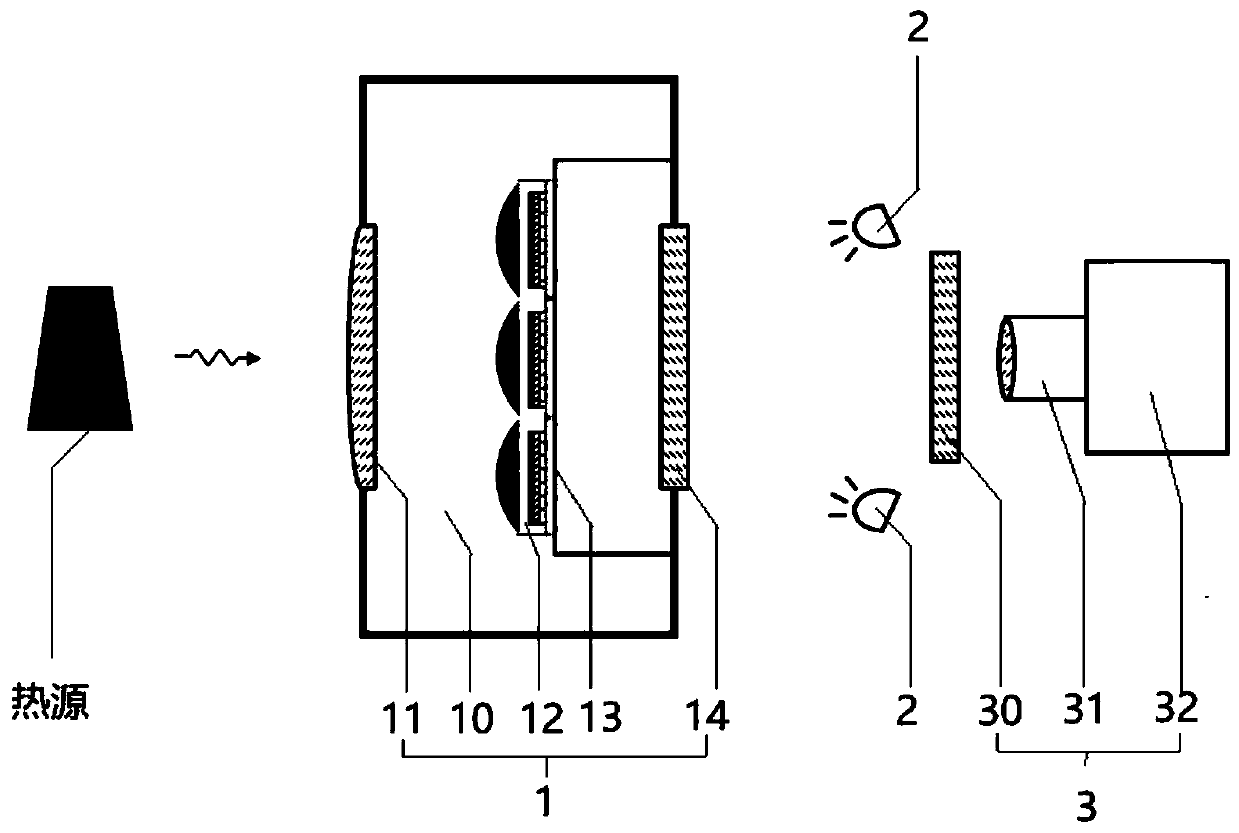
[0025] see figure 1 , figure 1 It is a schematic structural diagram of a preferred embodiment of an uncooled optical readout infrared thermal imaging system. As shown in the figure, the uncooled optical readout infrared thermal imaging system includes a front-end structure 1, The excitation light source 2 and the back-end structure 3, wherein the front-end structure 1 includes a vacuum chamber 10 and a lens 11, an infrared detection array 12, a sample stage 13 and a rearview mirror located in the vacuum chamber 10 and arranged in sequence from front to back ...


PUM


Abstract

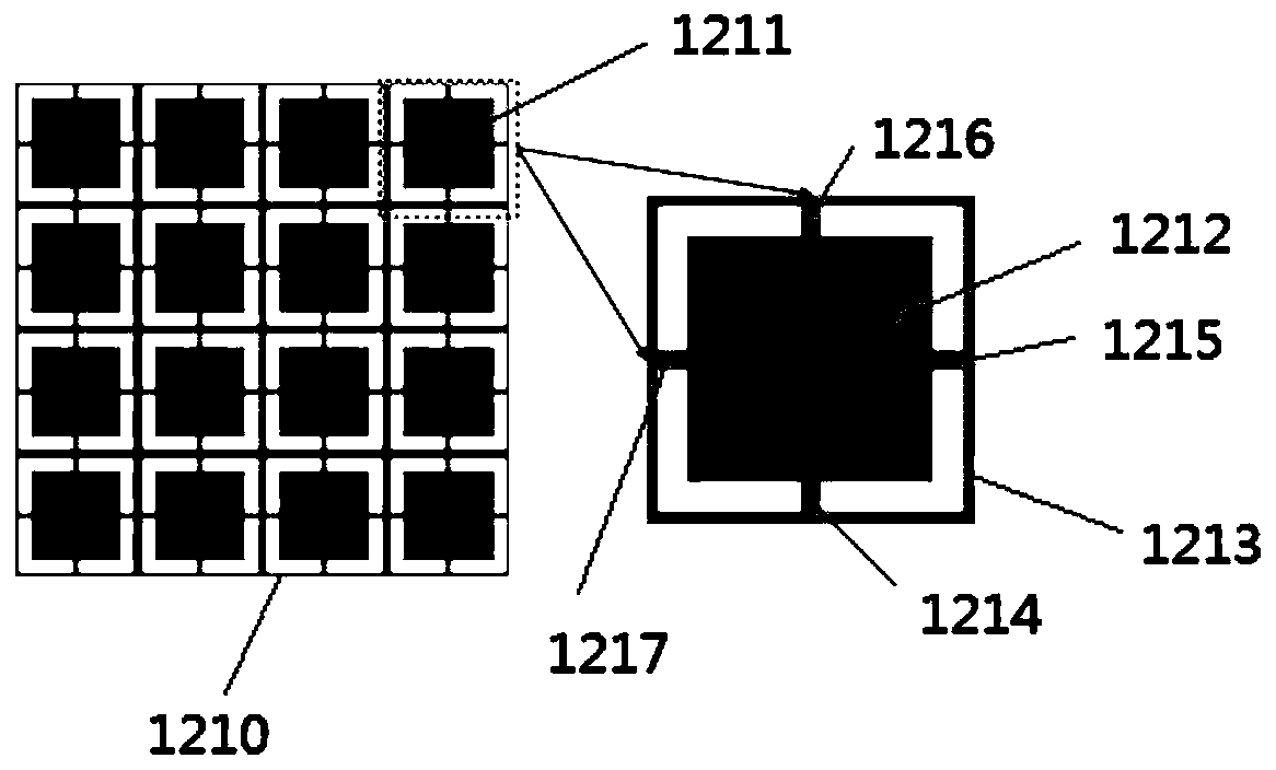
The invention discloses an uncooled optical readout type infrared thermal imaging system. The system comprises a front-end structure, an excitation light source and a rear-end structure which are sequentially arranged from front to back, wherein the front end structure comprises a vacuum cavity, and a lens, an infrared detection array, a sample table and a rearview mirror which are sequentially arranged in the vacuum cavity from front to back; the central positions of the lens, the infrared detection array, the sample table and the rearview mirror are located on the same straight line; the infrared detection array comprises a plurality of detection units, and each detection unit comprises a supporting structure, a temperature-sensitive light-emitting layer, a reflecting layer, an absorbinglayer and a silicon micro lens which are sequentially arranged from bottom to top. The technical problems that an existing infrared imaging system is complex in structure and preparation process andhigh in cost are solved.

Description

technical field [0001] The invention relates to the technical field of infrared imaging, in particular to an uncooled optical readout infrared thermal imaging system. Background technique [0002] Any object in nature can emit infrared radiation when the temperature is higher than absolute zero. Infrared radiation refers to electromagnetic waves with a wavelength range of 0.75-1000 μm, also known as thermal radiation or infrared rays. Infrared thermal imaging is a non-contact, non-invasive, fast and efficient technology. By detecting infrared radiation and measuring the intensity of infrared radiation, humans can detect infrared bands. Infrared thermal imaging technology is often used in military reconnaissance, In the fields of satellite and aircraft remote sensing, it is often used in production quality inspection, medical diagnosis, vehicle night vision system and security monitoring in daily life. [0003] Infrared imaging systems can be divided into photoelectric detec...

Claims


Application Information

Patent Timeline
Patent Type & Authority Applications(China)
IPC IPC(8): G01N21/35
CPCG01N21/35
Inventor 王敏李松
Owner SOUTH UNIVERSITY OF SCIENCE AND TECHNOLOGY OF CHINA
Learn More