
Preparation method of JFET device, JFET device and layout structure of JFET device

A device, N-type technology, applied in semiconductor/solid-state device manufacturing, semiconductor devices, electrical components, etc., can solve problems such as voltage breakdown

Pending Publication Date: 2020-07-07
SHANGHAI HUAHONG GRACE SEMICON MFG CORP
View PDF4 Cites 0 Cited by
  • Summary
  • Abstract
  • Description
  • Claims
  • Application Information

AI Technical Summary

Problems solved by technology

[0007] The present application provides a preparation method of a JFET device, a JFET device and its layout structure, which can solve the problem that the JFET device provided in the related art is prone to voltage breakdown after the gate oxide layer is thinned

Method used


Image

  • Preparation method of JFET device, JFET device and layout structure of JFET device
  • Preparation method of JFET device, JFET device and layout structure of JFET device
  • Preparation method of JFET device, JFET device and layout structure of JFET device

Examples


Embodiment Construction

[0069] The technical solutions in this application will be clearly and completely described below in conjunction with the accompanying drawings. Apparently, the described embodiments are part of the embodiments of this application, not all of them. Based on the embodiments in this application, all other embodiments obtained by persons of ordinary skill in the art without making creative efforts belong to the scope of protection of this application.

[0070] In the description of this application, it should be noted that the terms "center", "upper", "lower", "left", "right", "vertical", "horizontal", "inner", "outer" etc. The indicated orientation or positional relationship is based on the orientation or positional relationship shown in the drawings, and is only for the convenience of describing the present application and simplifying the description, rather than indicating or implying that the referred device or element must have a specific orientation, use a specific orientati...


PUM

PropertyMeasurementUnit
lengthaaaaaaaaaa

Abstract

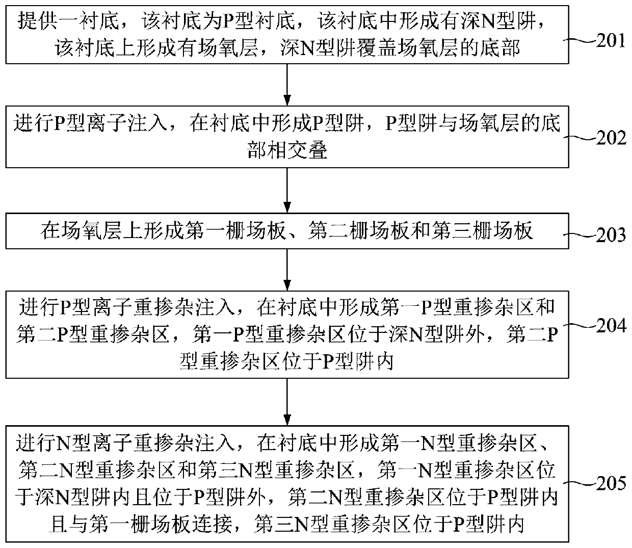
The invention discloses a preparation method of a JFET device, the JFET device and a layout structure of the JFET device, and the method comprises: providing a substrate, forming a deep N-type trap inthe substrate, and forming a field oxide layer on the substrate; forming a P-type well in the substrate, wherein the P-type well is overlapped with the bottom of the field oxide layer; forming a first gate field plate, a second gate field plate and a third gate field plate on the field oxide layer; forming a first P-type heavily doped region and a second P-type heavily doped region in the substrate; and forming a first N-type heavily doped region, a second N-type heavily doped region and a third N-type heavily doped region in the substrate. In the process of preparing the JFET device, the P-type trap expands towards the drain electrode and wraps part of the area at the bottom of the field oxide layer, so that the electric field intensity of the field oxide layer close to the first grid electrode is reduced, the breakdown risk after the field oxide layer is thinned is reduced to a certain extent, and the reliability of the JFET device is improved.

Description

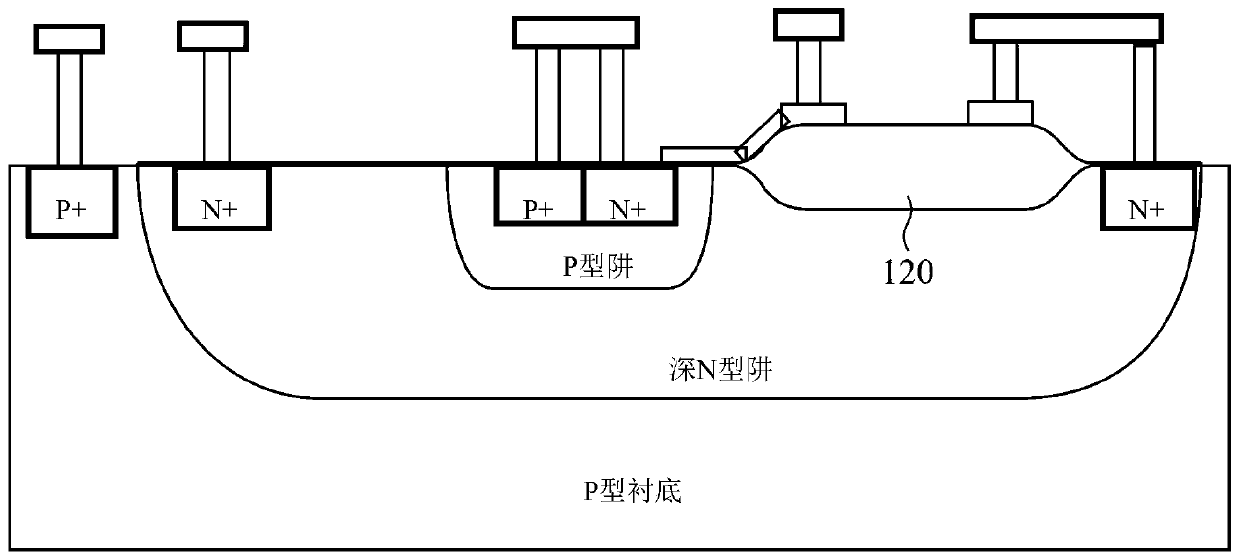
technical field [0001] The present application relates to the technical field of semiconductor manufacturing, in particular to a preparation method of a JFET device, a JFET device and a layout structure thereof. Background technique [0002] Junction Field-Effect Transistor (JFET) is a three-terminal active device with amplification function composed of Gate, Source and Drain of PN junction. Its working principle is to control the output current by changing the conductivity of the channel through the voltage. [0003] The BCD (Bipolar-CMOS-DMOS) process is a process for fabricating bipolar transistor (BipolarJunction Transistor, BJT) devices, complementary metal-oxide semiconductor (Complementary Metal-Oxide Semiconductor, CMOS) devices and DMOS devices on the same chip (Die). Devices manufactured by BCD process are widely used in power management, display drive, automotive electronics, industrial control and other fields. [0004] refer to figure 1 , which shows a schema...

Claims


Application Information

Patent Timeline
Patent Type & Authority Applications(China)
IPC IPC(8): H01L21/337H01L29/808H01L29/423H01L29/40
CPCH01L29/66893H01L29/808H01L29/404H01L29/42364
Inventor 蔡莹金锋
Owner SHANGHAI HUAHONG GRACE SEMICON MFG CORP
Learn More