
High-voltage high-capacity split reactance type current limiter

A technology of split reactor and split reactance, which is applied in the direction of transformer/inductor coil/winding/connection, transformer/inductor parts, circuits, etc., which can solve the problems of low port withstand voltage and large footprint

Active Publication Date: 2020-07-07
INST OF ELECTRICAL ENG CHINESE ACAD OF SCI
View PDF25 Cites 4 Cited by
  • Summary
  • Abstract
  • Description
  • Claims
  • Application Information

AI Technical Summary

Problems solved by technology

[0004] The purpose of the present invention is to overcome the disadvantages of the existing split reactors, such as low port withstand voltage ratio, multiple modules connected in series, and large floor space, etc., and propose a high-voltage and large-capacity split reactance current limiter

Method used


Image

  • High-voltage high-capacity split reactance type current limiter
  • High-voltage high-capacity split reactance type current limiter
  • High-voltage high-capacity split reactance type current limiter

Examples


Embodiment Construction

[0016] The present invention will be further described below in conjunction with the accompanying drawings and specific embodiments.

[0017] figure 1 Shown is the equivalent circuit diagram of a conventional multi-module split reactance current limiter. Such as figure 1 As shown, the multi-module split reactance current limiter is composed of multiple high-coupling split reactor modules and multiple fast circuit breaker modules.

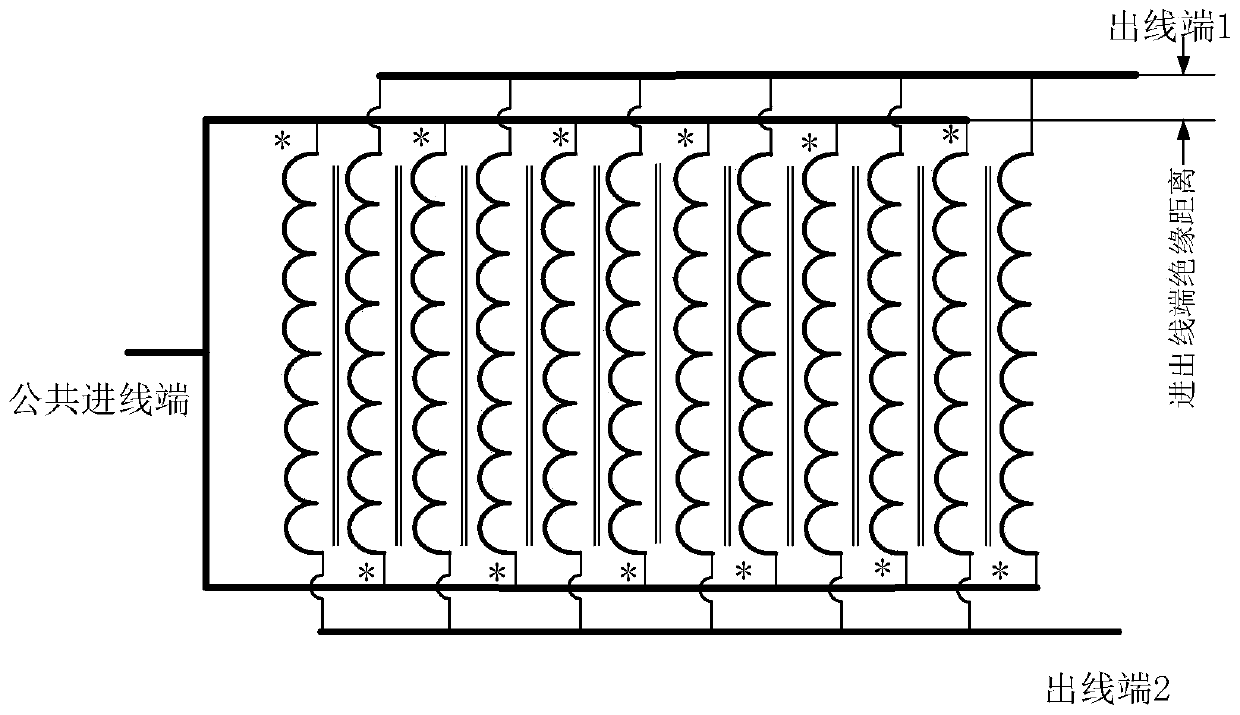
[0018] figure 2 Shown is the equivalent circuit diagram of the embodiment of the high-voltage and large-capacity split reactance current limiter of the present invention. Such as figure 2 As shown, the high-voltage split reactance current limiter is composed of a high-voltage split reactor and a multi-fracture fast circuit breaker. The high-voltage split reactor adopts a high-end withstand voltage coil structure and outlet mode; the operating mechanism of the multi-fracture fast circuit breaker adopts an electromagnetic repulsion mechanism, a...


PUM

PropertyMeasurementUnit
Thicknessaaaaaaaaaa

Abstract

A high-voltage high-capacity split reactance type current limiter adopts a three-phase independent structure. The single-phase split reactance type current limiter is composed of a single high-voltagesplit reactor and a single multi-break quick vacuum circuit breaker, and the multi-break quick vacuum circuit breaker is located on one arm of the split reactor. The high-voltage split reactor is composed of an inner reactor winding, an outer reactor winding and an insulating baffle. The inner reactor winding and the outer reactor winding are both of a multi-encapsulation parallel dry-type air-core reactor structure. The winding directions of the inner reactor winding and the outer reactor winding are opposite; the wire inlet ends at the bottom share one wiring terminal; the wire outlet endsat the top are mutually independent; and a wire outlet end (1) at the top of the inner reactor winding is arranged on the inner side of the inner reactor winding, a wire outlet end (2) at the top of the outer reactor winding is arranged on the outer side of the outer reactor winding, the inner reactor winding and the outer reactor winding are isolated by an insulating baffle, and the insulating baffle is higher than the inner reactor winding and the outer reactor winding.

Description

technical field [0001] The invention relates to a split reactance current limiter applied to short-circuit fault current limiter. Background technique [0002] With the rapid development of the national economy, the level of short-circuit current in power grids at all levels continues to increase, and the insufficient breaking capacity of power grid fault short-circuit current has increasingly become an important bottleneck problem restricting the development of power grids. Considering the insufficient breaking capacity of circuit breakers, the solution of installing fault current limiters in the grid has received a lot of attention. The fault current limiter has a small impedance under normal conditions, and the impedance becomes large to limit the current when a short-circuit fault occurs. The current fault current limiter technology mainly includes split reactance current limiter, series resonant current limiter, solid-state current limiter and other current limiting te...

Claims


Application Information

Patent Timeline
IPC IPC(8): H02H9/02H01F17/02H01F27/32H01F27/29H01F27/40
CPCH02H9/021H01F17/02H01F27/323H01F27/29H01F27/40
Inventor 邱清泉肖立业张志丰滕玉平张京业靖立伟周微微
Owner INST OF ELECTRICAL ENG CHINESE ACAD OF SCI
Learn More