
Stud welding mechanism

A welding mechanism and stud technology, applied in welding equipment, auxiliary welding equipment, welding/cutting auxiliary equipment, etc., can solve the problems of low efficiency of manual stud welding, unsatisfactory use requirements, poor quality control, etc., and achieve optimization Utilize the flow direction of the site and logistics, save equipment investment, and avoid current shunting affecting the welding effect

Pending Publication Date: 2020-07-10
广州富士汽车整线集成有限公司
View PDF0 Cites 0 Cited by
  • Summary
  • Abstract
  • Description
  • Claims
  • Application Information

AI Technical Summary

Problems solved by technology

Robot automatic stud welding has a large investment, manual stud welding has low efficiency, and the quality is not easy to control. Moreover, robot automatic stud welding needs to switch between spot welding guns and stud welding guns, and the robot needs to add gun changing trays, feeders, etc. equipment, and in the case of separate procedures for stud welding and spot welding, the logistics of the parts also flow separately, the welding efficiency is not high, and it does not meet the requirements of people. Therefore, we propose a stud welding mechanism

Method used


Image

  • Stud welding mechanism
  • Stud welding mechanism
  • Stud welding mechanism

Examples


Embodiment Construction

[0025] The following will clearly and completely describe the technical solutions in the embodiments of the present invention with reference to the accompanying drawings in the embodiments of the present invention. Obviously, the described embodiments are only some, not all, embodiments of the present invention.

[0026] In describing the present invention, it should be understood that the terms "upper", "lower", "front", "rear", "left", "right", "top", "bottom", "inner", " The orientation or positional relationship indicated by "outside", etc. is based on the orientation or positional relationship shown in the drawings, and is only for the convenience of describing the present invention and simplifying the description, rather than indicating or implying that the referred device or element must have a specific orientation, so as to Specific orientation configurations and operations, therefore, are not to be construed as limitations on the invention.

[0027] A stud welding mec...


PUM


Abstract

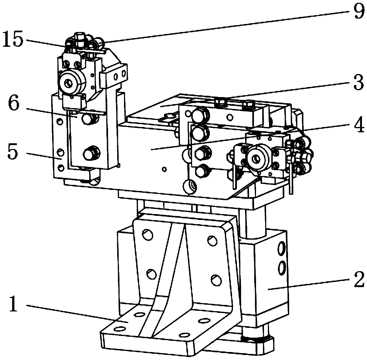
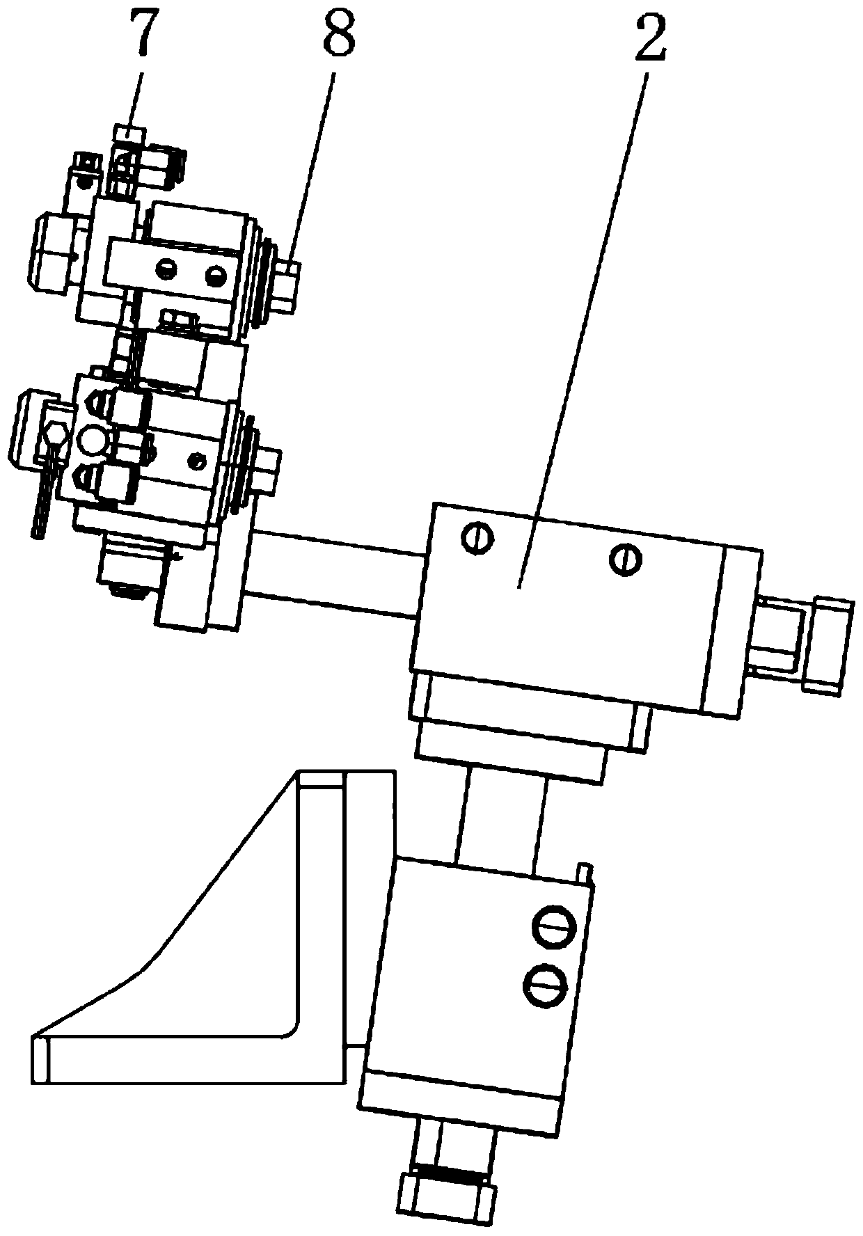
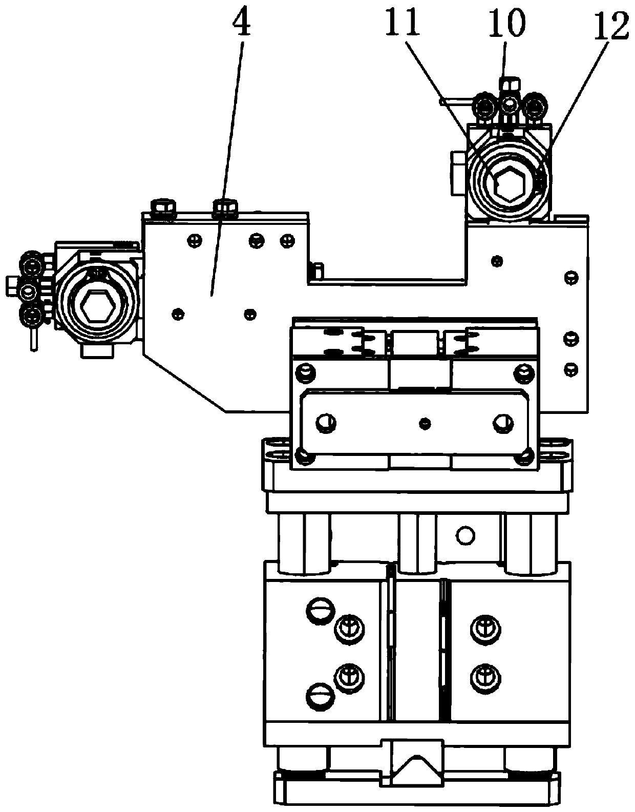
The invention discloses a stud welding mechanism comprising an angle seat, a first double guide rod cylinder and a second double guide rod cylinder; push plates are arranged in the first double guiderod cylinder and the second double guide rod cylinder, and the first double guide rod cylinder is fixedly installed on the angle seat; the lower end of the outside surface of the second double guide rod cylinder is fixedly installed at the telescopic end of the push plate on the first double guide rod cylinder; and the telescopic end of the push plate on the second double guide rod cylinder is fixedly provided with a connecting plate. According to the stud welding mechanism stated in the invention, online stud welding of spot welding and stud welding in the same working procedure is achieved;the stud welding mechanism has the advantages that the equipment investment, equipment procurement cost and gun replacement time are saved, and a logistics transportation route can be optimized; the transportation process is simplified, and the transportation time is reduced; the production efficiency is improved greatly, and the problem that the high automation and the cost reduction are not compatible is solved; and the stud welding mechanism has better application prospects.

Description

technical field [0001] The invention relates to the field of automobiles, in particular to a stud welding mechanism. Background technique [0002] The history of the application of stud welding technology in my country is not long, but with the rapid development of my country's economy and the continuous improvement of the manufacturing industry, the model is updated rapidly, the output and variety of automobiles have increased significantly, and the competition in the automobile market has become increasingly fierce. Stud welding technology It is being adopted by more and more domestic enterprises. [0003] At present, in the automobile industry, the common forms of stud welding of automobile sheet metal are robot automatic stud welding and manual stud welding. Robotic automatic stud welding has a large investment, manual stud welding has low efficiency and poor quality control, and robot automatic stud welding needs to switch between spot welding guns and stud welding guns...

Claims


Application Information

Patent Timeline
Patent Type & Authority Applications(China)
IPC IPC(8): B23K37/00
CPCB23K37/00B23K37/003
Inventor 黄庆财吴平安
Owner 广州富士汽车整线集成有限公司
Learn More