
A production process of heat-insulating concrete

A production process and concrete technology, which is applied in the production process field of heat-insulating concrete, can solve the problems of no heat insulation effect, and achieve a remarkable effect of heat insulation

Active Publication Date: 2022-04-15
青岛金方豪绿色建筑工程科技有限公司
View PDF14 Cites 0 Cited by
  • Summary
  • Abstract
  • Description
  • Claims
  • Application Information

AI Technical Summary

Problems solved by technology

[0003] The purpose of the present invention is to provide a production process of heat-insulating concrete to solve the problem that generally does not have heat-insulating effect in the above-mentioned background technology

Method used

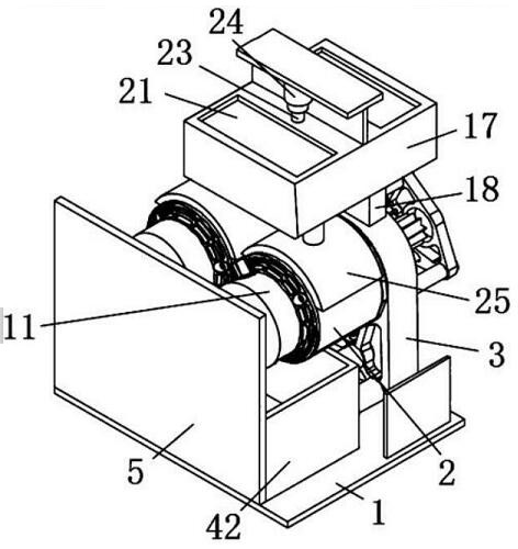
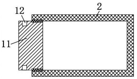
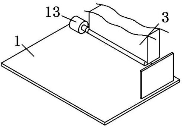

Image

  • A production process of heat-insulating concrete
  • A production process of heat-insulating concrete
  • A production process of heat-insulating concrete

Examples


Embodiment 1

[0053] A production process of heat-insulating concrete, the specific steps of which include:

[0054] The parts by weight are: 20 parts by weight of cement, 24 parts by weight of sand, 23 parts by weight of coarse aggregate, 15 parts by weight of fine aggregate, 18 parts by weight of water and 8 parts by weight of glass fiber chopped strands for subsequent use;

[0055] Place cement, sand, coarse aggregate, fine aggregate, and water in the first storage space 20 of the processing equipment, and place glass fiber chopped strands in the second storage space 20 of the processing equipment;

[0056] The first hydraulic rod 24 located above the first storage space 20 works to drive the movement of the material retaining plate 22 through the fixed rod 23. When the material retaining plate 22 moves upward, the material retaining plate 22 is located in the storage space 20, thereby facilitating the storage space 20. Cement, sand, coarse aggregate, fine aggregate, and water in the con...

Embodiment 2

[0080] In Example 1, "20 parts by weight of cement, 24 parts by weight of sand, 23 parts by weight of coarse aggregate, 15 parts by weight of fine aggregate, 18 parts by weight of water and 8 parts by weight of glass fiber chopped strands" were changed to "10 parts by weight of cement Parts by weight, 8 parts by weight of sand, 12 parts by weight of coarse aggregate, 13 parts by weight of fine aggregate, 13 parts by weight of water and 2 parts by weight of glass fiber chopped strands", and the rest are the same as in Example 1.

Embodiment 3

[0082] In Example 1, "20 parts by weight of cement, 24 parts by weight of sand, 23 parts by weight of coarse aggregate, 15 parts by weight of fine aggregate, 18 parts by weight of water and 8 parts by weight of glass fiber chopped strands" were changed to "15 parts by weight of cement Parts by weight, 20 parts by weight of sand, 18 parts by weight of coarse aggregate, 17 parts by weight of fine aggregate, 16 parts by weight of water and 5 parts by weight of glass fiber chopped strands", and the rest are the same as in Example 1.

[0083] The "fixed connection" described in the present invention means that the two parts connected to each other are fixed together, generally by means of welding, screwing or gluing; "rotational connection" means that the two parts are connected together And can move relatively.


PUM


Abstract

The invention discloses a heat-insulating concrete production process. The specific steps of the production process include: weighing parts by weight: 10-20 parts by weight of cement, 8-24 parts by weight of sand, and 12-23 parts by weight of coarse aggregate , 13-15 parts by weight of fine aggregate, 13-18 parts by weight of water and 2-8 parts by weight of glass fiber chopped strands for subsequent use; In the storage space, the glass fiber chopped strands are placed in the second storage space of the processing equipment; the first hydraulic rod located above the first storage space works to drive the movement of the baffle plate through the fixed rod, when the baffle plate moves upwards , the baffle plate is located in the storage space, so that the cement, sand, coarse aggregate, fine aggregate, and water in the storage space flow into the mixing tank through the discharge frame; the invention realizes the uniform mixing of materials and makes the concrete It also has the effect of heat insulation.

Description

technical field [0001] The invention relates to the technical field of heat-insulating concrete, in particular to a production process of heat-insulating concrete. Background technique [0002] Concrete is one of the most important civil engineering materials today. It is a kind of artificial stone made of cementitious materials, granular aggregates, water, and admixtures and admixtures added when necessary, prepared in a certain proportion, uniformly stirred, compacted, cured and hardened. Concrete has the characteristics of rich raw materials, low price and simple production process, so its consumption is increasing. At the same time, concrete also has the characteristics of high compressive strength, good durability, and a wide range of strength grades. These characteristics make it widely used, not only in various civil engineering, but also in shipbuilding, machinery industry, marine development, geothermal engineering, etc. Concrete is also an important material, but...

Claims


Application Information

Patent Timeline
Patent Type & Authority Patents(China)
IPC IPC(8): C04B28/00B28C5/20B28C7/06B28C7/12B28C7/16B28B1/52C04B14/42
CPCC04B28/00B28C5/20B28C5/2045B28C5/2072B28C7/06B28C7/126B28C7/161B28B1/52C04B14/06C04B14/00C04B14/42
Inventor 王淑彦
Owner 青岛金方豪绿色建筑工程科技有限公司
Learn More