
Engine oil dilution calculation method

A calculation method and technology of engine oil, applied in the direction of engine lubrication, mechanical equipment, engine components, etc., can solve the problems affecting the performance of diesel engines, shortening the service life of diesel engines, increasing the cost of use, etc., to reduce the dilution rate of engine oil, improve the use effect, The effect of saving user cost

Active Publication Date: 2020-07-10
无锡伟博汽车科技有限公司
View PDF6 Cites 4 Cited by
  • Summary
  • Abstract
  • Description
  • Claims
  • Application Information

AI Technical Summary

Problems solved by technology

When this method is used, not only does it fail to distinguish the factors that cause oil dilution, but also the oil change cycle cannot distinguish the user's operating conditions, including operating conditions (cargo capacity, vehicle speed), environmental conditions (altitude, temperature), after-treatment regeneration time and The frequency of regeneration and the replacement of engine oil with the minimum oil change mileage increase the user's use cost, and although diesel oil is injected into the cylinder, although it does not participate in the combustion in the cylinder, part of it will adhere to the cylinder wall and pass through the gap between the cylinder wall and the piston. The gap between the oil and the oil will flow to the oil pan, which increases the dilution rate of the engine oil. Mixing the engine oil with diesel oil will cause the viscosity value of the engine oil to decrease, which will affect the lubricating performance of the engine oil and the service life of the engine oil, thereby affecting the performance of the diesel engine and shortening the service life of the diesel engine. At the same time, the user cannot be reminded to change the oil in time, and the use effect is not good.

Method used


Image

  • Engine oil dilution calculation method
  • Engine oil dilution calculation method
  • Engine oil dilution calculation method

Examples


Embodiment Construction

[0023] The present invention will be described in further detail below in conjunction with the accompanying drawings.

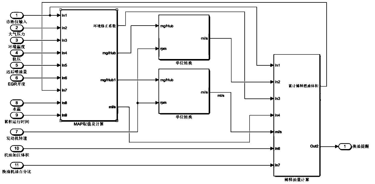
[0024] A calculation method for engine oil dilution, comprising the following steps:

[0025] (1) Calculate the fuel volume V0 (ml) in the oil when the oil needs to be replaced according to the oil replacement index given by the lubricating oil company and the total amount of oil filled;

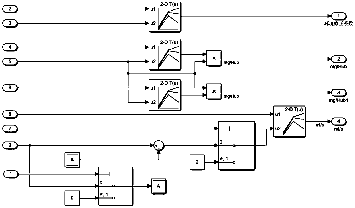
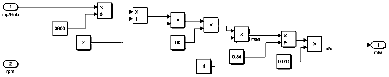
[0026] (2) According to the rail pressure and the MAP output oil dilution coefficient of the far rear fuel injection quantity q, multiply the far rear fuel injection quantity q to obtain the base fuel quantity in the engine oil, and obtain the fuel growth rate in the engine oil per unit time after unit conversion q1(mg / s);

[0027] (3) Carry out environmental factor correction, the fuel growth rate q1 is multiplied by the coefficient a obtained from the revised MAP of the ambient pressure and the ambient temperature, and the fuel growth rate a*q1 (ml / s) in the engine oil a...


PUM


Abstract

The invention discloses an engine oil dilution calculation method. The engine oil dilution calculation method comprises the following steps of (1) calculating the fuel oil quantity V0(ml) of engine oil when the engine oil needs to be replaced; (2) outputting an engine oil dilution coefficient according to the rail pressure and the MAP of the far-backward oil injection quantity q, and conducting unit conversion to obtain the fuel oil growth rate q1(mg / s) of the engine oil in unit time; (3) correcting environmental factors to obtain the fuel oil growth rate a*q1(ml / s) of the oil in the engine oil after correction of the environmental factors; (4) correcting the EGR rate, and obtaining the fuel oil growth rate q2(ml / s) with the corrected EGR rate after unit conversion; (5) correcting oil volatilization, and obtaining the fuel oil evaporation rate q3(ml / s) in unit time; (6) calculating the fuel oil growth rate of the engine oil in unit time to be Q=a*q1+q2-q3(ml / s); (7) obtaining the oil content V1(ml) of the engine oil through the Q and the time integral; and (8) displaying a prompt for replacing engine oil on an instrument when V1>V0. Compared with the prior art, the engine oil dilution calculation method has the advantages of low cost and good use effect.

Description

technical field [0001] The invention relates to the technical field of engine oil, in particular to a calculation method for engine oil dilution. Background technique [0002] At present, the far rear injection regeneration technology generally adopted by light vehicles, the diesel fuel sprayed from the far rear of the injector does not participate in the combustion in the cylinder, and stays in the cylinder for a period of time, and then is discharged into the after-treatment DOC with the exhaust gas through the exhaust valve. , It reacts with oxygen in the DOC to release heat to increase the temperature before the DPF to achieve the purpose of regeneration. Since the ECU (Electronic Control Unit) does not yet have the logic of calculating oil dilution, it can only be converted into oil change mileage according to the results of oil dilution tests in various environments (altitude, temperature, etc.), and take the smallest oil change mileage Change the oil. When this meth...

Claims


Application Information

Patent Timeline
Patent Type & Authority Applications(China)
IPC IPC(8): F01M11/10
CPCF01M11/10F01M2011/14
Inventor 李朋张晓斌徐万里
Owner 无锡伟博汽车科技有限公司
Learn More