Self-testing MEMS thermopile infrared detector

A technology of infrared detectors and thermopiles, which is applied in the direction of electric radiation detectors, etc., to achieve the effects of improving response rate and detection rate, reducing test cost, and reducing time-consuming

Inactive Publication Date: 2020-07-10
JIANGSU HINOVAIC TECH CO LTD
View PDF8 Cites 6 Cited by
  • Summary
  • Abstract
  • Description
  • Claims
  • Application Information

AI Technical Summary

Problems solved by technology

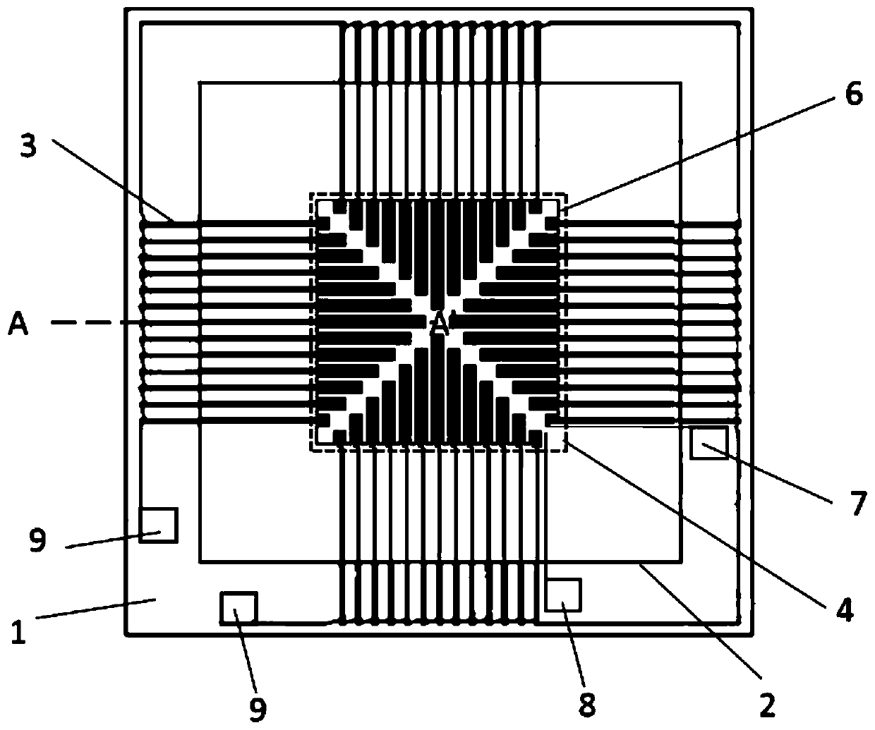
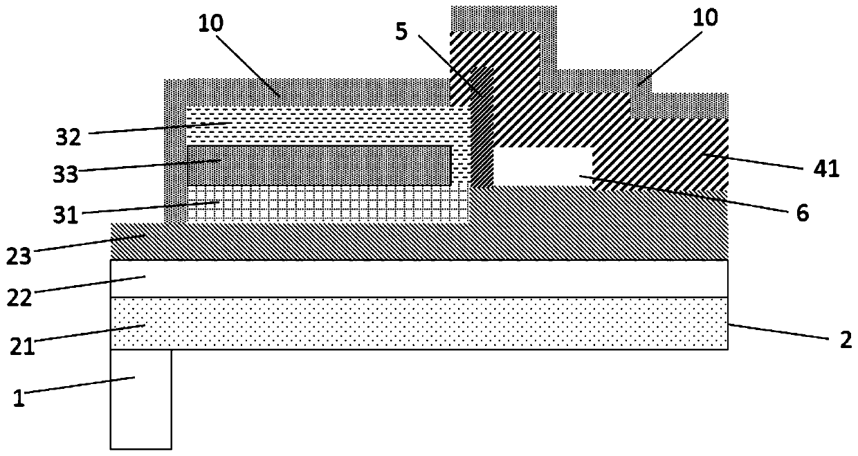
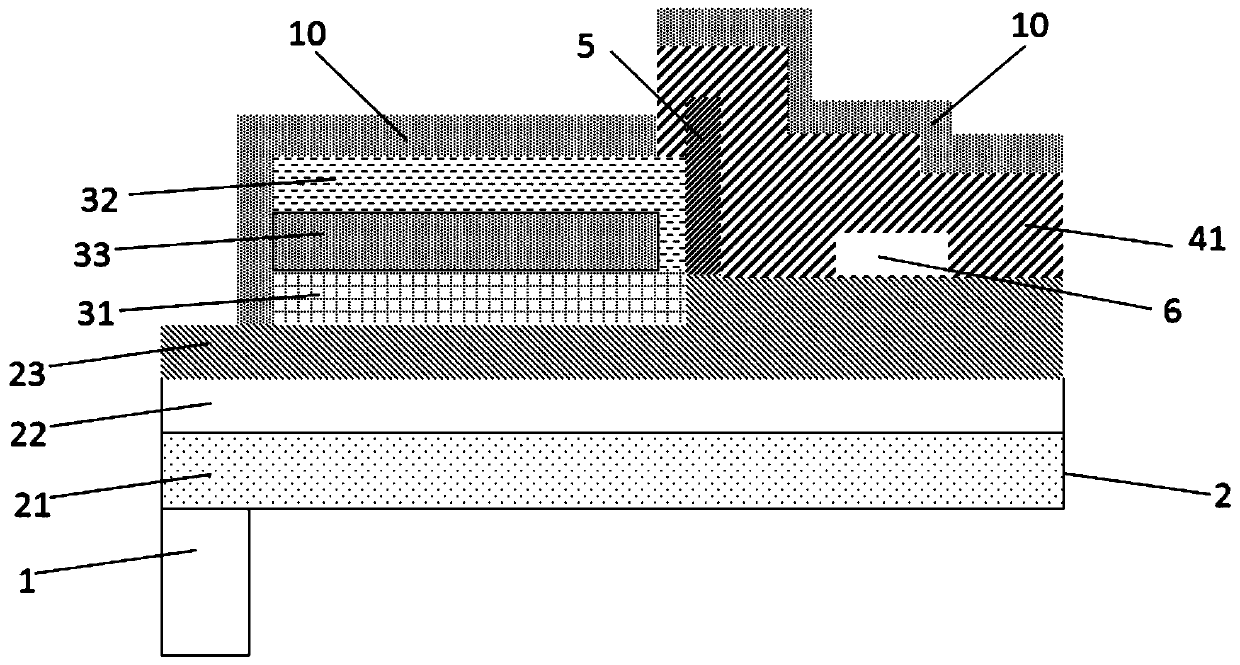
[0004] Therefore, the technical problem to be solved in the present invention is to overcome the defect that the existing MEMS thermopile sensor needs to be tested with special equipment before use, thereby providing a self-test MEMS thermopile infrared detector

Method used


Image

  • Self-testing MEMS thermopile infrared detector
  • Self-testing MEMS thermopile infrared detector
  • Self-testing MEMS thermopile infrared detector

Examples


Embodiment Construction

[0031] The technical solutions of the present invention will be clearly and completely described below in conjunction with the accompanying drawings. Apparently, the described embodiments are some of the embodiments of the present invention, but not all of them. Based on the embodiments of the present invention, all other embodiments obtained by persons of ordinary skill in the art without making creative efforts belong to the protection scope of the present invention.

[0032] In the description of the present invention, it should be noted that the orientation or positional relationship indicated by the terms "upper", "lower", "inner", "outer" and the like are based on the orientation or positional relationship shown in the accompanying drawings, and are only for It is convenient to describe the present invention and simplify the description, but does not indicate or imply that the device or element referred to must have a specific orientation, be constructed and operate in a ...


PUM

PropertyMeasurementUnit
thicknessaaaaaaaaaa
thicknessaaaaaaaaaa
thicknessaaaaaaaaaa

Abstract

The invention provides a self-test MEMS thermopile infrared detector. The detector comprises a substrate and a supporting layer stacked on a surface of the substrate, a thermopile assembly and an infrared absorption unit are arranged on the surface, away from the substrate, of the supporting layer, the infrared absorption unit makes contact with the thermopile assembly to achieve thermal connection between the thermopile assembly and the infrared absorption unit, and an electric insulation structure is arranged between the thermopile assembly and the infrared absorption unit; a self-checking component is also included, when a pressure applying end of the self-checking component is externally connected with a power supply and a grounding end of the self-checking component is grounded, generated heat is conducted to the thermopile assembly through the infrared absorption unit to generate a potential difference so that an electrical response rate of a thermopile can be obtained; an electrical response rate difference value obtained by applying pressure twice is compared with a response rate difference value preset threshold value so that whether the device works normally can be determined; and a self-test function of the MEMS thermopile detector is realized, use of special equipment for testing is avoided, test cost is effectively reduced, time consumption of a device test processis reduced, and the use of the device is more convenient.

Description

technical field [0001] The invention relates to the technical field of thermopile sensors, in particular to a self-testing MEMS thermopile infrared detector. Background technique [0002] The working principle of the thermopile detector is based on the Seebeck effect. It detects the infrared electromagnetic waves emitted by objects and converts them into measurable electrical signals to characterize the physical temperature. Taking advantage of thermopile environmental adaptability, small size, and convenience, infrared thermopile sensors are widely used in infrared search, non-contact temperature measurement, security, smart appliances, harmful gas monitoring and other industries. With the development of microelectronics technology, the concept of Micro-Electro-Mechanical System (MEMS: Micro-Electro-MechanicalSystem) has been widely concerned. With MEMS technology, semiconductor materials and processes are applied to thermopile sensors, forming MEMS thermopile sensors. ME...

Claims


Application Information

Patent Timeline
Patent Type & Authority Applications(China)
IPC IPC(8): G01J5/20
CPCG01J5/20
Inventor 丁雪峰张琛琛毛海央
Owner JIANGSU HINOVAIC TECH CO LTD
Why Eureka
Try Eureka