
Fire inducing element, millisecond electric detonator without conventional delay device and processing method of millisecond electric detonator

A technology of delay device and ignition element, which is applied in fuzes, weapon accessories, non-explosive/non-thermal components, etc., can solve the problems of high technical requirements of operators, lack of large-scale promotion conditions, and cumbersome wiring of electronic detonators. , to ensure the probability of ignition, reduce the harm to workers' health, and solve the effect of poor detonation ability

Pending Publication Date: 2020-07-14
ANHUI UNIV OF SCI & TECH
View PDF7 Cites 1 Cited by
  • Summary
  • Abstract
  • Description
  • Claims
  • Application Information

AI Technical Summary

Problems solved by technology

Although the above-mentioned electronic detonators have their own advantages, there are also certain disadvantages. The wiring of electronic detonators in engineering use is cumbersome, involving programming knowledge, and requires high technical requirements for operators. Used in mines, the production cost is much higher than that of ordinary detonators, and the conditions for large-scale promotion are not yet available

Method used


Image

  • Fire inducing element, millisecond electric detonator without conventional delay device and processing method of millisecond electric detonator
  • Fire inducing element, millisecond electric detonator without conventional delay device and processing method of millisecond electric detonator
  • Fire inducing element, millisecond electric detonator without conventional delay device and processing method of millisecond electric detonator

Examples


Embodiment Construction

[0031] Embodiments of the present invention are described in detail below, examples of which are shown in the drawings, wherein the same or similar reference numerals designate the same or similar elements or elements having the same or similar functions throughout. The embodiments described below by referring to the figures are exemplary and are intended to explain the present invention and should not be construed as limiting the present invention.

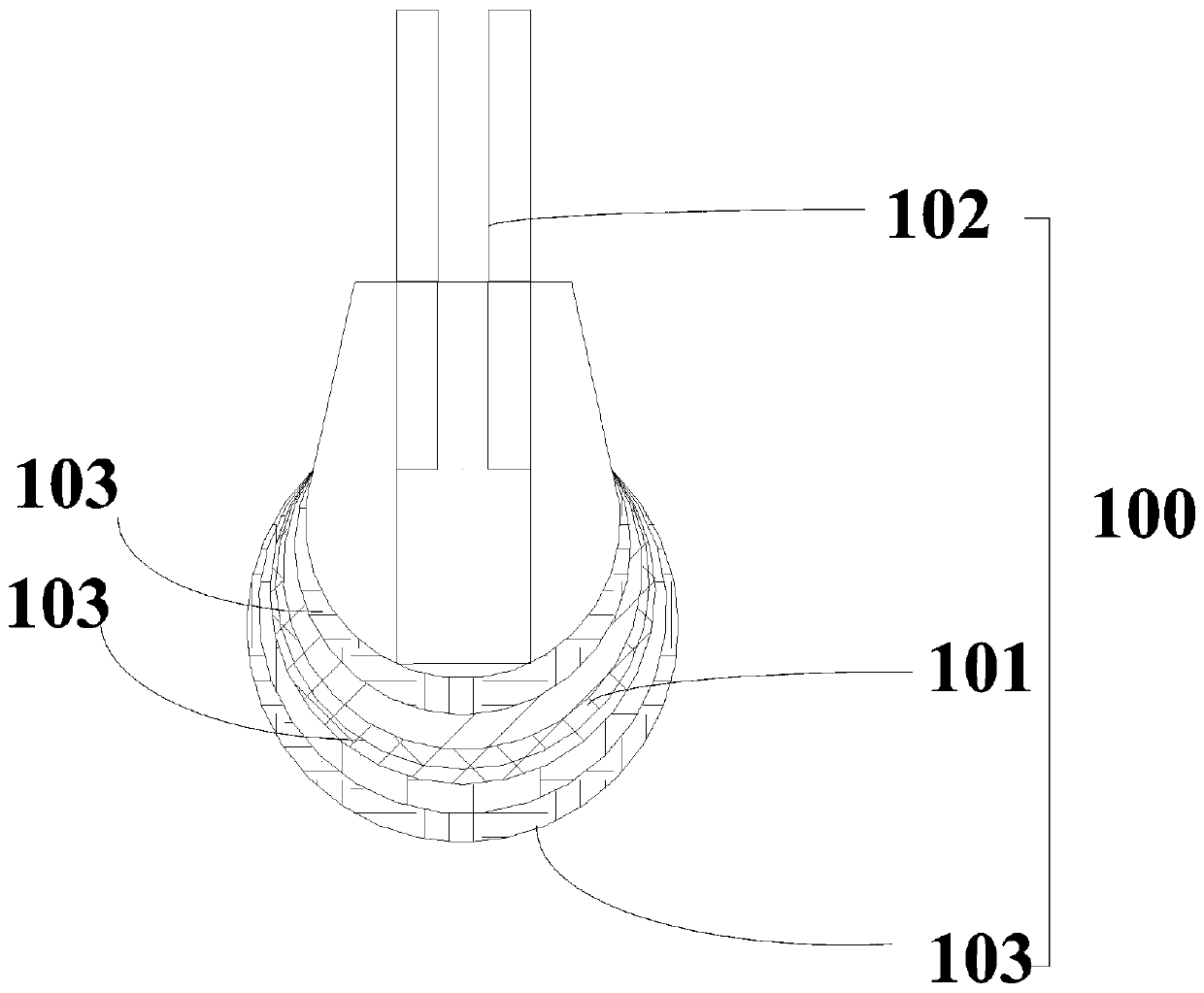
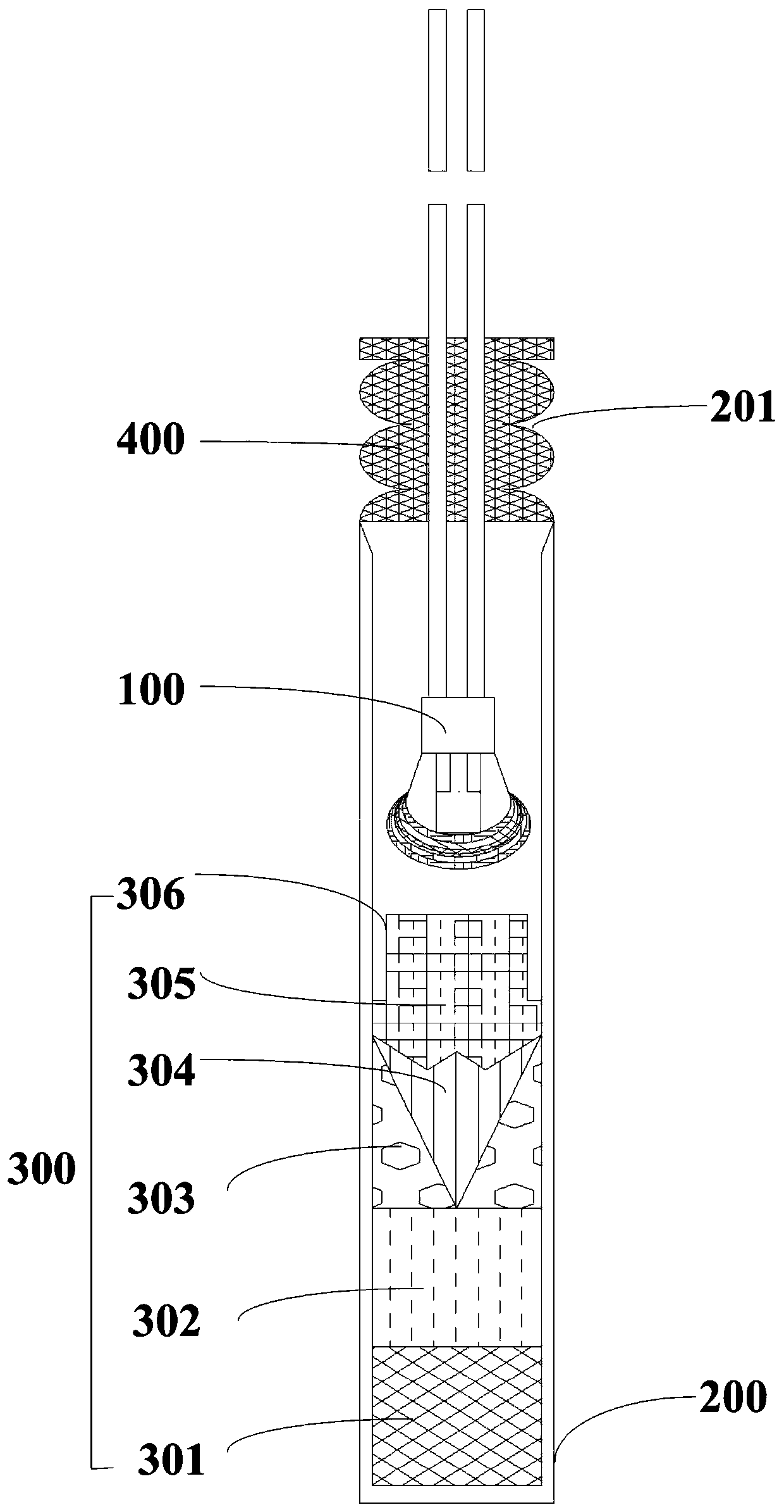
[0032] In one embodiment of the present invention, see attached figure 1 It shows a structural diagram of a millisecond electric detonator ignition element provided by the present invention, including: a drug head 101, a leg line 102 and a combustible agent 103; the drug head 101 is in a semicircular shape, and its internal bridge wire is connected to the leg line 102, and A combustible agent 103 is cross-bonded on the drug head 101 . Advantageously, the combustible agent 103 is magnesium powder or aluminum powder, which is cros...


PUM


Abstract

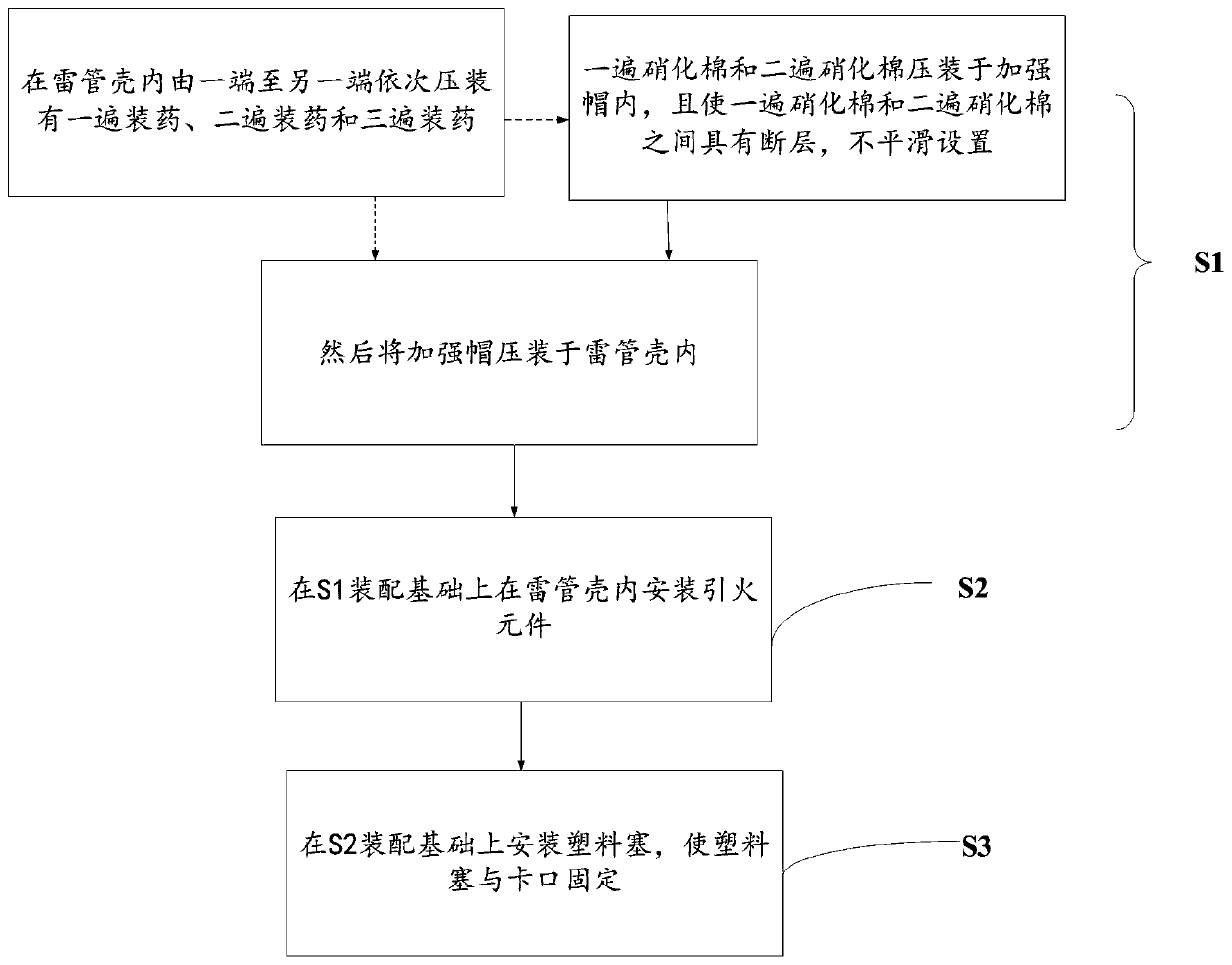
The invention relates to a fire inducing element, a millisecond electric detonator without a conventional delay device and a processing method of the millisecond electric detonator. A contact surfacebetween primary nitrocotton and secondary nitrocotton is not smooth, so that stable combustion is changed to the reaction of detonation after the ignition of the primary nitrocotton; the use amount ofthe nitrocotton is controlled, at the same time, the ignition probability of the detonator is guaranteed, the problem that the traditional detonator production wastewater treatment is difficult is solved, the production cost of enterprises is reduced, the harm of the production process to health of workers is reduced, the labor intensity is reduced, and a delay element in a traditional detonatoris canceled; a combustible agent which is crossly smeared on a gunpowder head is ignited after the gunpowder head is ignited, the detonator delay time depends on the time required by the combustion ofthe combustible agent which is crossly smeared on the gunpowder head, and the production cost of the detonator is reduced; the advantages of stable ignition efficiency, small pollution, simple process and high workmanship are achieved; and at the same time, the defects of poor detonation capacity of an existing non-explosive detonator and low safety of the essence are overcome.

Description

technical field [0001] The invention relates to the technical field of detonating devices, and more specifically relates to an ignition element, a millisecond electric detonator without a conventional delay device and a processing method thereof. Background technique [0002] At this stage, my country's industrial detonators generally use dinitrodiazonium phenol, lead azide, nickel hydrazine nitrate, etc. as the primary explosives. With the continuous application of advanced blasting technology in the civil explosive industry, the performance requirements for detonating materials in the industry have been further improved, but as far as detonating materials are concerned, their essential unsafety still exists, such as the use of dinitrodiazophenol and The electric detonator with lead azide as the priming agent is still difficult to overcome the influence of external current, and the electric detonator may also have accidents due to the high sensitivity of the priming agent d...

Claims


Application Information

Patent Timeline
IPC IPC(8): F42C19/12F42C19/08C06B23/00C06B27/00C06B25/20C06B25/28
CPCF42C19/12F42C19/0803C06B23/001C06B27/00C06B25/20C06B25/28
Inventor 谢兴华张兴炎周慧生王啸刘上豪崔钿孙鹏张良杰杨恒李增源汪泉吴红波李雪交杜明燃
Owner ANHUI UNIV OF SCI & TECH
Learn More