A photoelectric connection device

A photoelectric connection and interface technology, applied in the field of communication, can solve the problems of increasing the volume of electronic equipment and increasing the complexity of electronic equipment structure, and achieve the effect of large-scale deployment, low cost and high application flexibility

Active Publication Date: 2021-07-16
HUAWEI TECH CO LTD
View PDF3 Cites 0 Cited by
  • Summary
  • Abstract
  • Description
  • Claims
  • Application Information

AI Technical Summary

Problems solved by technology

However, setting an additional POE interface on the electronic device will increase the structural complexity of the electronic device and increase the volume of the electronic device

Method used


Image

  • A photoelectric connection device
  • A photoelectric connection device
  • A photoelectric connection device

Examples


Embodiment Construction

[0035] The application scenarios of the present application embodiment will be described below in conjunction with the drawings.

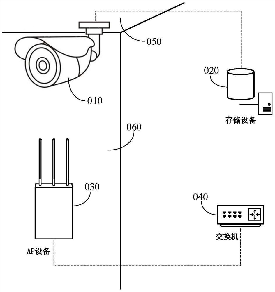
[0036] figure 1 It is an electronic device installation scenario showcase. Such as figure 1 As shown, the access point device (AP) 030, the network camera 010, the traffic light, the micro base station can be mounted in the room of the ceiling 050, wall 060, and a building wall surface, pole, etc. These electronic devices can establish network connections with other network devices such as fiber, twisted pair, etc., for example: access point devices connected to the remote switch device 040, network camera connecting to the remote storage device 020, traffic Signal or the like to connect to the remote control device, etc.

[0037] In addition to the network connection, electronic devices also require power supply to supply power to work.

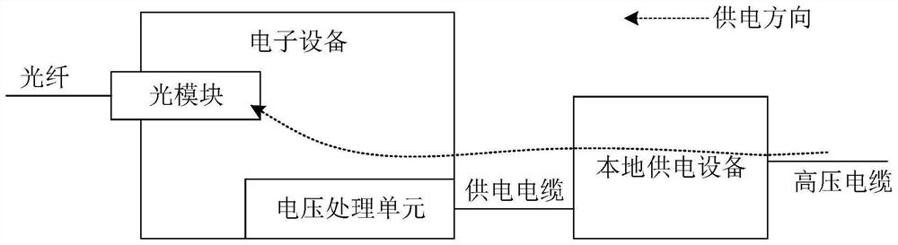
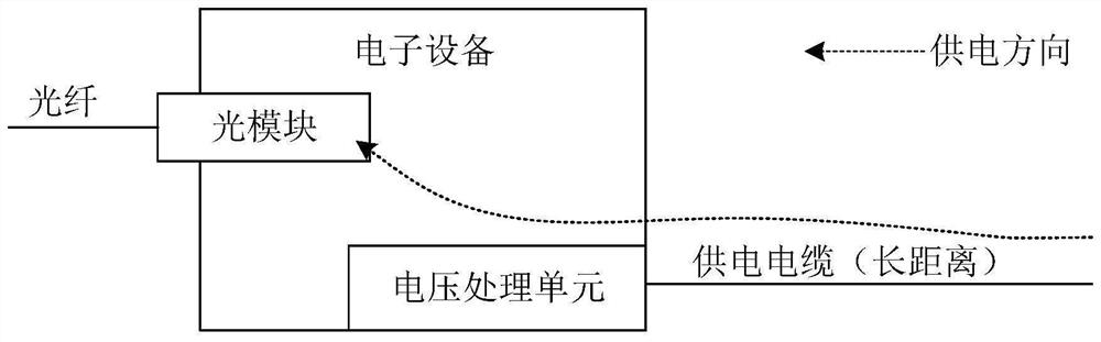
[0038] When equipped with a power supply in the vicinity of the electronic device, the electronic device can be u...


PUM


Abstract

The present application provides an optical connection device, such as an optical module, including: an optical signal interface arranged at one end of the casing and an electrical signal interface arranged at the other end of the casing. The optical signal interface and the electrical signal interface pass through the The photoelectric processing module is coupled. Wherein, the optical signal interface end is provided with a first insulator, the electrical signal interface end is provided with a second insulator, the first insulator includes at least two first metal contacts for coupling to the POE power supply, and the second insulator includes At least two second metal contacts exposed outside the shell, the first metal contact and the second metal contact are electrically connected through a conductive medium wrapped with an insulating medium. The photoelectric connection device provided by the embodiment of the present application can not only send and receive optical / electrical signals, but also couple the remote POE power supply to the electronic equipment to supply power to the electronic equipment, so that the electronic equipment does not need additional POE interfaces, which is beneficial to reduce The size of the electronic device.

Description

Technical field [0001] The present application relates to the field of communication, and more particularly to a photoelectric connection device. Background technique [0002] Access Point, AP, webcam and other electronic devices are typically installed in corporate parks, indoor ceiling, architectural walls, etc., which typically do not have power supply to operate for electronic equipment, so, The power supply of these electronic devices is generally implemented by the Power Over Ethernet, PoE. [0003] Ethernet power is a technique that can transmit power to electronic devices in an Ethernet. Ethernet power supply generally uses a photovoltaic mixing cable to transmit optical signals and electrical energy in which optical signals are used to enable network communication, and electrical energy is used for power supply for remote electronic devices. The photovoltaic mixing cable consists of fibers and cables. , Light signals and electrical energy are implemented by fibers and ca...

Claims


Application Information

Patent Timeline
Patent Type & Authority Patents(China)
IPC IPC(8): G02B6/42
CPCG02B6/4246G02B6/4256H04L12/10H04L12/40045
Inventor 陈磊吴援朋舒亮
Owner HUAWEI TECH CO LTD
Why Eureka
Try Eureka