EBG surface-loaded millimeter wave SIW horn antenna

A horn antenna and millimeter-wave technology, applied in waveguide horns, antenna arrays that are energized separately, antennas, etc., can solve problems such as difficult matching, low gain, and poor matching performance of dielectric substrates, and achieve high antenna gain, improved gain, and structure simple effect

Pending Publication Date: 2020-07-14
CHINA ELECTRONICS TECH GRP CORP NO 14 RES INST
View PDF0 Cites 11 Cited by
  • Summary
  • Abstract
  • Description
  • Claims
  • Application Information

AI Technical Summary

Problems solved by technology

However, due to factors such as thin dielectric sheet thickness and high dielectric constant, the millimeter-wave H-plane SIW horn antenna also has disadvantages such as difficult matching, high back lobe level, and low gain. It is diff

Method used


Image

  • EBG surface-loaded millimeter wave SIW horn antenna
  • EBG surface-loaded millimeter wave SIW horn antenna
  • EBG surface-loaded millimeter wave SIW horn antenna

Examples


Embodiment 1

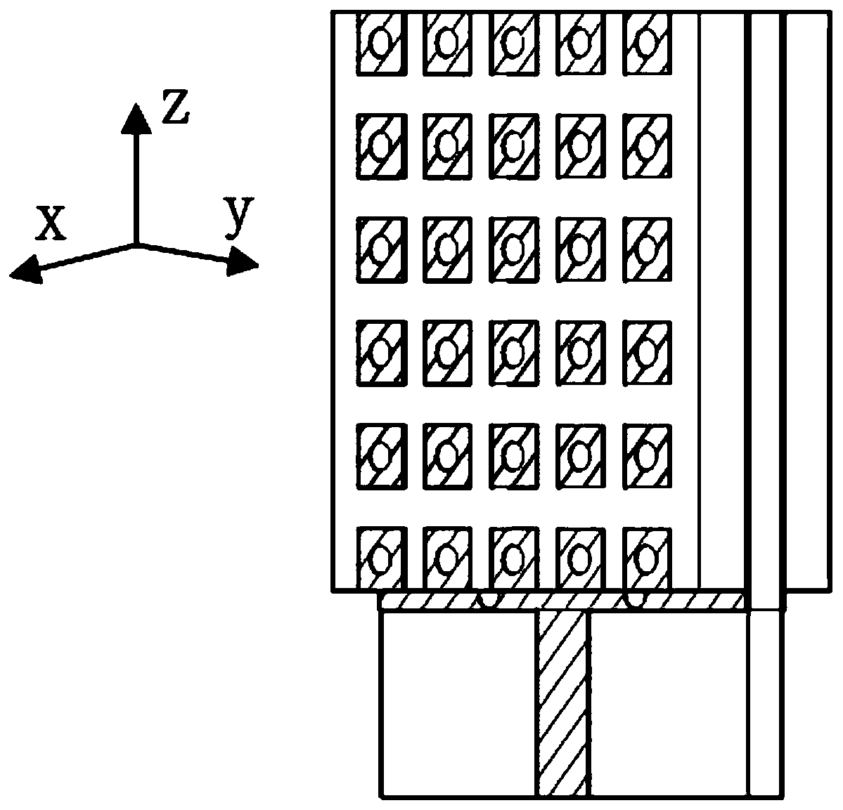
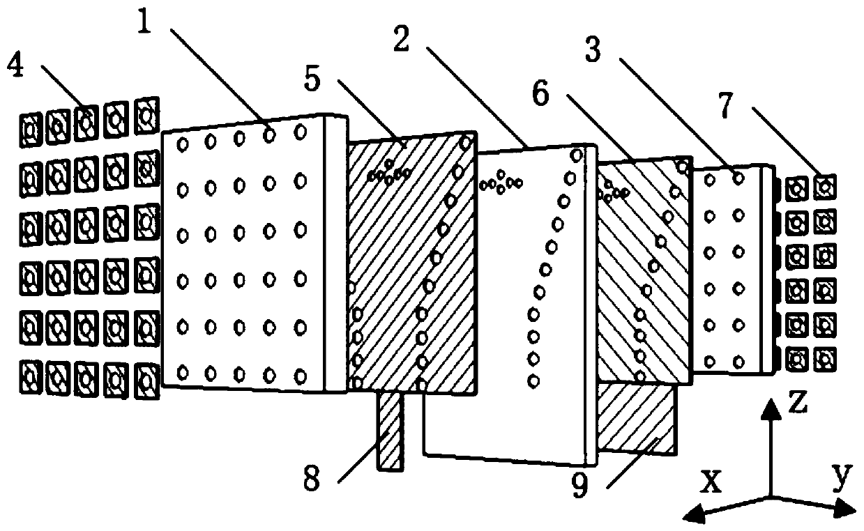
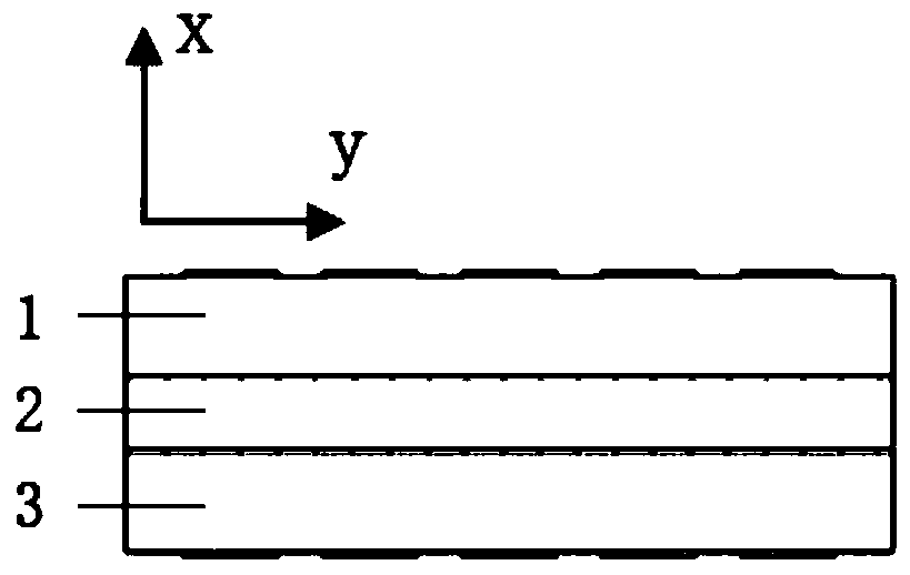
[0032] An embodiment of the present invention is a millimeter-wave SIW horn antenna loaded on the surface of an EBG.

[0033] Such as Figure 1 ~ Figure 4 As shown, the millimeter-wave SIW horn antenna loaded on the EBG surface of this embodiment includes: an upper EBG layer metal plate 4, an upper EBG layer dielectric substrate 1, an upper radiation layer metal plate 5, and a radiation layer dielectric substrate 2 pressed together in sequence. , the lower radiation layer metal plate 6 , the lower EBG layer dielectric substrate 3 and the lower EBG layer metal plate 7 . The metal plate 8 of the feed layer is coplanarly interconnected with the metal plate 5 of the upper radiation layer, and the metal ground 9 of the feed layer is interconnected with the metal plate 6 of the lower radiation layer. The upper EBG layer dielectric substrate 1, the radiation layer dielectric substrate 2, and the lower EBG layer dielectric substrate 3 are all made of LTCC (Low Temperature Co-fired Ce...


PUM


Abstract

The invention discloses an EBG surface-loaded millimeter wave SIW horn antenna and belongs to the technical field of antenna microwaves. The antenna comprises an upper EBG layer metal plate (4), an upper EBG layer dielectric substrate (1), an upper radiation layer metal plate (5), a radiation layer dielectric substrate (2), a lower radiation layer metal plate (6), a lower EBG layer dielectric substrate (3), a lower EBG layer metal plate (7), a feed layer metal plate (8) and feed layer metal ground (9); the upper EBG layer metal plate (4), the upper EBG layer dielectric substrate (1), the upperradiation layer metal plate (5), the radiation layer dielectric substrate (2), the lower radiation layer metal plate (6), the lower EBG layer dielectric substrate (3) and the lower EBG layer metal plate (7) are laminated together in sequence; the feed layer metal plate (8) is in coplanar interconnection with the upper radiation layer metal plate (5); the feed layer metal ground (9) is in coplanarinterconnection with the lower radiation layer metal plate (6); a metal patch array and metalized via holes (10) are distributed on the upper EBG layer metal plate (4); the upper EBG layer metal plate and the lower EBG layer metal plate are consistent in structure; and the upper EBG layer dielectric substrate and the lower EBG layer dielectric substrate are consistent in structure; and a plurality of SIW horn cavity metallized through holes (11) are equivalent to a rectangular metal waveguide. The EBG surface-loaded millimeter wave SIW horn antenna is high in front-to-back ratio, high in gainand small in caliber.

Description

technical field [0001] The invention belongs to the field of antenna microwave technology, in particular to a millimeter-wave SIW (Substrate integrated waveguide, dielectric integrated waveguide) horn antenna loaded with an EBG (Electromagnetic BandGap, electromagnetic bandgap) structure. Background technique [0002] With the increasing tension of the electromagnetic spectrum in the traditional microwave band, wireless applications in the millimeter wave band are becoming more and more extensive. In wireless applications in the millimeter wave band, such as point-to-point high-speed communication, high-resolution radar, etc., the demand for antenna miniaturization, high integration, and low cost is increasing. [0003] The traditional horn antenna has the advantages of high front-to-back ratio (front-to-back ratio = forward energy / backward energy), high gain, etc., but its disadvantages such as high profile and large volume limit its application in millimeter waves, especia...

Claims


Application Information

Patent Timeline
IPC IPC(8): H01Q1/38H01Q1/48H01Q1/50H01Q19/10H01Q3/30H01Q13/02H01Q21/06H01Q21/00
CPCH01Q1/38H01Q1/48H01Q1/50H01Q3/30H01Q13/02H01Q19/10H01Q21/0006H01Q21/064
Inventor 张金平杨溢周志鹏
Owner CHINA ELECTRONICS TECH GRP CORP NO 14 RES INST
Why Eureka
Try Eureka