
Bridgeless buck-boost AC-to-DC converter

A DC converter, buck-boost technology, applied in the direction of converting AC power input to DC power output, irreversible AC power input conversion to DC power output, high-efficiency power electronic conversion, etc., can solve high output voltage, high cost, The number of components is too large to achieve the effect of improving the conversion efficiency and avoiding the sound of the power-on relay

Active Publication Date: 2020-07-14
亚瑞源科技(深圳)有限公司 +2
View PDF7 Cites 4 Cited by
  • Summary
  • Abstract
  • Description
  • Claims
  • Application Information

AI Technical Summary

Problems solved by technology

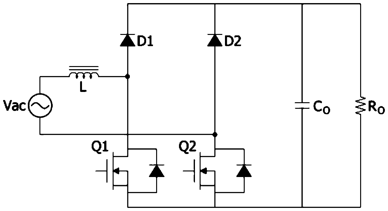
[0005] In order to solve the problems of bridge rectification loss, switching surge current, high output voltage, excessive number of components and high cost in the prior art, the present invention provides a bridgeless buck-boost AC-to-DC converter

Method used


Image

  • Bridgeless buck-boost AC-to-DC converter
  • Bridgeless buck-boost AC-to-DC converter
  • Bridgeless buck-boost AC-to-DC converter

Examples


specific Embodiment 1

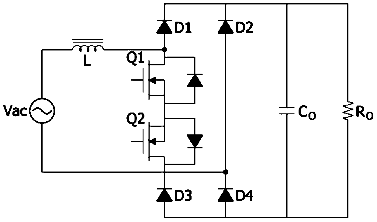
[0036] Specific embodiment one: please refer to Figure 9 As shown, the bridgeless buck-boost AC-to-DC converter is used to convert an AC input power Vac, and then provide a DC output power Vo with a positive terminal and a negative terminal on the output capacitor Co. The bridgeless buck-boost AC-DC converter includes a first circuit 10 , a second circuit 20 , a third diode D3 and a fourth diode D4 .

[0037] The first line 10 has a first end, a second end and a third end. The first terminal is coupled to the first terminal of the AC input power Vac, the second terminal is coupled to the ground terminal, and the third terminal is coupled to the positive terminal or the negative terminal of the DC output power Vo. The second line 20 has a first end, a second end and a third end, the first end is coupled to the second end of the AC input power supply Vac, the second end is coupled to the ground end, and the third end is coupled to The positive terminal or the negative termina...


PUM


Abstract

The invention relates to a bridgeless buck-boost AC-to-DC converter. The converter is used for converting an AC input power source so as to provide a DC output power source with a positive electrode end and a negative electrode end on an output capacitor. The converter is characterized in that the first end of a first circuit is coupled with the first end of the AC input power source; the second end of the first circuit is coupled with a grounding end; the third end of the first circuit is coupled with the positive electrode end or the negative electrode end of the DC output power source; thefirst end of a second circuit is coupled with the second end of the AC input power source; the second end of the second circuit is coupled with the grounding end; the third end of the second circuit is coupled with the positive electrode end or the negative electrode end of the DC output power source; a third diode is coupled between the first end of the second circuit and the grounding end; and afourth diode is coupled between the first end of the first circuit and the grounding end. According to the bridgeless buck-boost AC-to-DC converter of the invention, conversion efficiency can be improved; a capacitor with low withstand voltage can be selected as the output end of the direct current output power source, a surge current limiter for starting up does not need to be added. The converter can be operated under a discontinuous conduction mode, a continuous conduction mode and a critical conduction mode.

Description

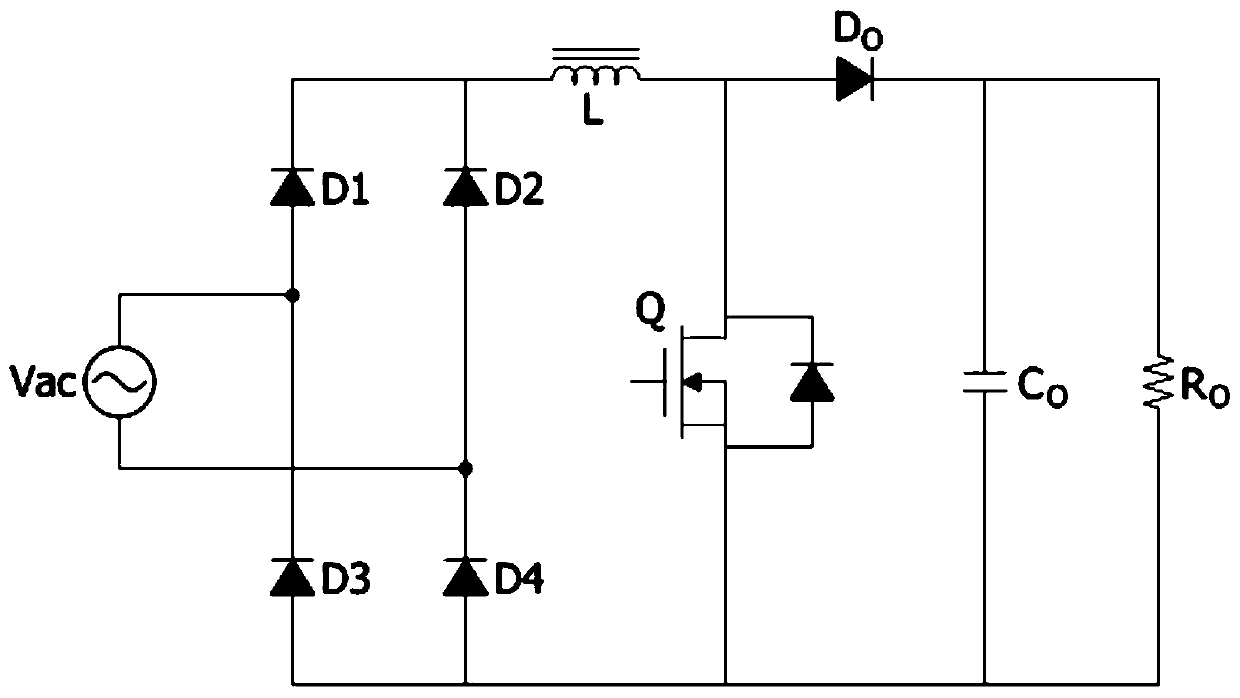
technical field [0001] The invention relates to an AC-to-DC converter, in particular to a bridgeless step-down AC-to-DC converter. Background technique [0002] The traditional boost power factor correction converter (BoostPFC) is still widely used in the industry because of its simple circuit structure. Its typical circuit structure is as follows: figure 1 shown. However, the step-up power factor correction converter has three disadvantages: First, the input must use a bridge rectifier diode, which makes the diode conduction loss account for a higher proportion of the total loss, and the lower the AC input voltage, it will bring more loss of efficiency. Second, since the output voltage of the step-up power factor correction converter must be higher than the peak value of the input AC power voltage, a 400-volt or even 450-volt electrolytic capacitor must be used, and the price of the electrolytic capacitor will also increase as the withstand voltage increases . Third, be...

Claims


Application Information

Patent Timeline
IPC IPC(8): H02M7/12H02M1/42
CPCH02M7/125H02M1/4225H02M1/0048H02M1/4291Y02B70/10
Inventor 洪宗良姚宇桐
Owner 亚瑞源科技(深圳)有限公司
Learn More