Eureka AIR delivers breakthrough ideas for toughest innovation challenges, trusted by R&D personnel around the world.

Funnel type smoke dust filtering device

A dust filtration, funnel-type technology, applied in the direction of dispersed particle filtration, separation method, dispersed particle separation, etc., can solve the problems of adjusting the size of the dust filter pores, increasing the pressure difference of the flue gas dust filter device, and not being able to effectively filter dust particles and impurities , to achieve the effect of increasing the reserved time and improving the filtering effect

Pending Publication Date: 2020-07-17
QINGDAO UNIV OF SCI & TECH
View PDF0 Cites 0 Cited by
  • Summary
  • Abstract
  • Description
  • Claims
  • Application Information

AI Technical Summary

Problems solved by technology

Before the chemical reaction is carried out, it is necessary to filter the impurity particles in the exhaust gas in various ways. The existing coarse filter devices are all fixed and unadjustable, but the diameters of the impurity particles in each type of flue gas are different. In the prior art The flue gas and dust filter device cannot adjust the size of its dust filter pores according to the type of flue gas, resulting in the occurrence of flue gas and dust filter devices that use too small dust to filter the pores to filter the soot containing impurity particles with excessively large diameters, resulting in increased flue gas and dust filtration The pressure difference inside and outside the device increases the air supply power of the smoke exhaust motor, or the smoke dust filter device with too large dust filter pores filters the smoke containing impurity particles with too small diameter, so that the dust particles in the smoke cannot be effectively filtered out Impurities

Method used


Image

  • Funnel type smoke dust filtering device
  • Funnel type smoke dust filtering device
  • Funnel type smoke dust filtering device

Examples


Embodiment

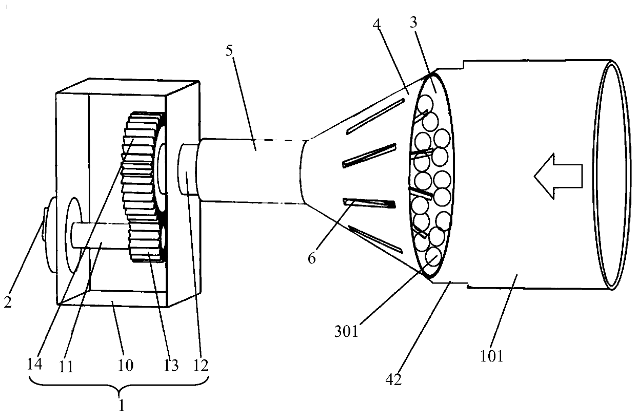
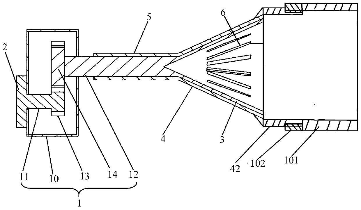
[0061] The embodiment of the present invention discloses a funnel-type flue gas dust filter device, the working principle is as follows:

[0062] The cylindrical cylinder 42 of the present invention is connected to the exhaust pipe 101, and the smoke flows from the exhaust pipe 101 to the filter funnel 3, and the scale turntable 2 is rotated so that the scale turntable 2 drives the input shaft 11 to rotate, thereby making the first cylindrical gear 13 is meshed with the second cylindrical gear 14 for transmission, so that the input shaft 11 drives the output shaft 12 to rotate through the gear transmission mode, and then the output shaft 12 drives the inner filter funnel 3 to rotate, and the outer filter funnel 4 of the present invention is connected to the exhaust pipe 101 keep still, so the present invention can control the position of the inner filter funnel 3 relative to the outer filter funnel 4 through the scale dial 2, thereby changing the position between the first filt...


PUM

PropertyMeasurementUnit
Diameteraaaaaaaaaa

Abstract

The invention discloses a funnel type smoke dust filtering device which is communicated with a smoke exhaust pipeline, and a scale turntable is positioned outside a gear box and is connected to an input shaft, an inner filtering funnel is located outside the gear box, a small head end of the inner filtering funnel is connected to an output shaft, a plurality of first filtering through holes are uniformly formed in the side wall of the inner filtering funnel in the circumferential direction, an outer filtering funnel sleeves the inner filtering funnel, a small head end of the outer filtering funnel is communicated with a sleeve, the sleeve sleeves an output shaft, a large head end of the outer filtering funnel is connected with a smoke exhaust pipeline, the smoke exhaust pipeline is communicated with a large head end of the inner filtering funnel, a plurality of second filtering through holes are evenly formed in the side wall of the outer filtering funnel in the circumferential direction, and the second filtering through holes and the first filtering through holes are communicated to form smoke discharging holes. The funnel type smoke dust filtering device can adjust dust filteringpores, so that the device can be suitable for filtering various types of flue gas.

Description

technical field [0001] The invention relates to the technical field of flue gas and dust filtering devices, in particular to a funnel-type flue gas and dust filtering device. Background technique [0002] With the continuous development of science and technology, people's living standards are also improving day by day, accompanied by serious environmental problems. Exhaust gas emitted by factories, vehicle exhaust, garbage burning, coal burning, etc. have greatly damaged the ecological environment. Solid particles such as dust, sulfur oxides, and nitrogen oxides in various exhaust gases have seriously polluted the air and human health. [0003] Various waste gas treatment methods include activated carbon adsorption method, catalytic combustion method, acid-base neutralization method, etc., using chemical methods to chemically react the impurity particles in the waste gas, so as to achieve the purpose of purification treatment. Before the chemical reaction is carried out, it...

Claims


Application Information

Patent Timeline
IPC IPC(8): B01D46/12B01D46/00
CPCB01D46/103B01D46/12B01D46/0002
Inventor 张元利张江辉崔建波
Owner QINGDAO UNIV OF SCI & TECH
Why Eureka
Eureka Blog
Learn More