Portable cable flaw detection robot system

A robot system and portable technology, applied in radio wave measurement systems, instruments, manipulators, etc., can solve the problems of undiscovered cable fault detection applications, local temperature rise insensitivity, and large laying investment, so as to save manpower and material resources and ensure power supply Reliability and operation cost reduction effects

Inactive Publication Date: 2020-07-17
CIVIL AVIATION UNIV OF CHINA
View PDF7 Cites 6 Cited by
  • Summary
  • Abstract
  • Description
  • Claims
  • Application Information

AI Technical Summary

Problems solved by technology

The online detection method is live detection, which can realize the monitoring of the cable status in the actual operating environment without the need for a power outage. Among them, the cable temperature monitoring is one of the important detection methods. At present, this part of the detection technology uses distributed optical fiber temperature measurement. The system measures the temperature of the cable sheath, obtains the conductor temperature through calculation, and then judges the type of cable fault through the conductor temperature, but it is not sensitive to local temperature rise caused by various defects, and is easily affected by ambient temperature, humidity, etc. High, large laying investment and other disadvantages
[0003] With the development of computer vision technology, image processing technology is gradually used in the field of cable detection, but the application of this technology in cable fault detection has not been found so far

Method used


Image

  • Portable cable flaw detection robot system
  • Portable cable flaw detection robot system
  • Portable cable flaw detection robot system

Examples


Embodiment Construction

[0016] The portable cable flaw detection robot system provided by the present invention will be described in detail below in conjunction with the accompanying drawings and specific embodiments.

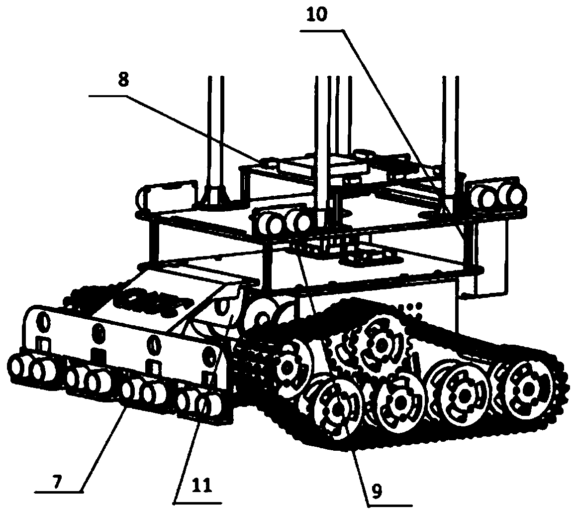
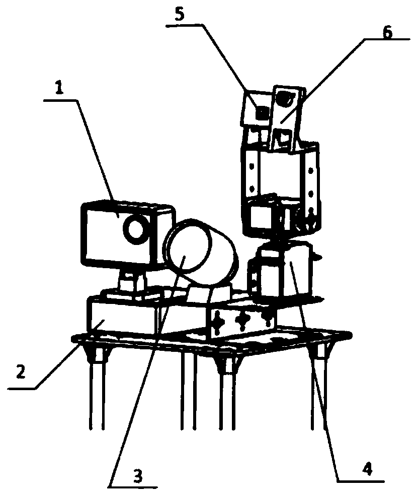
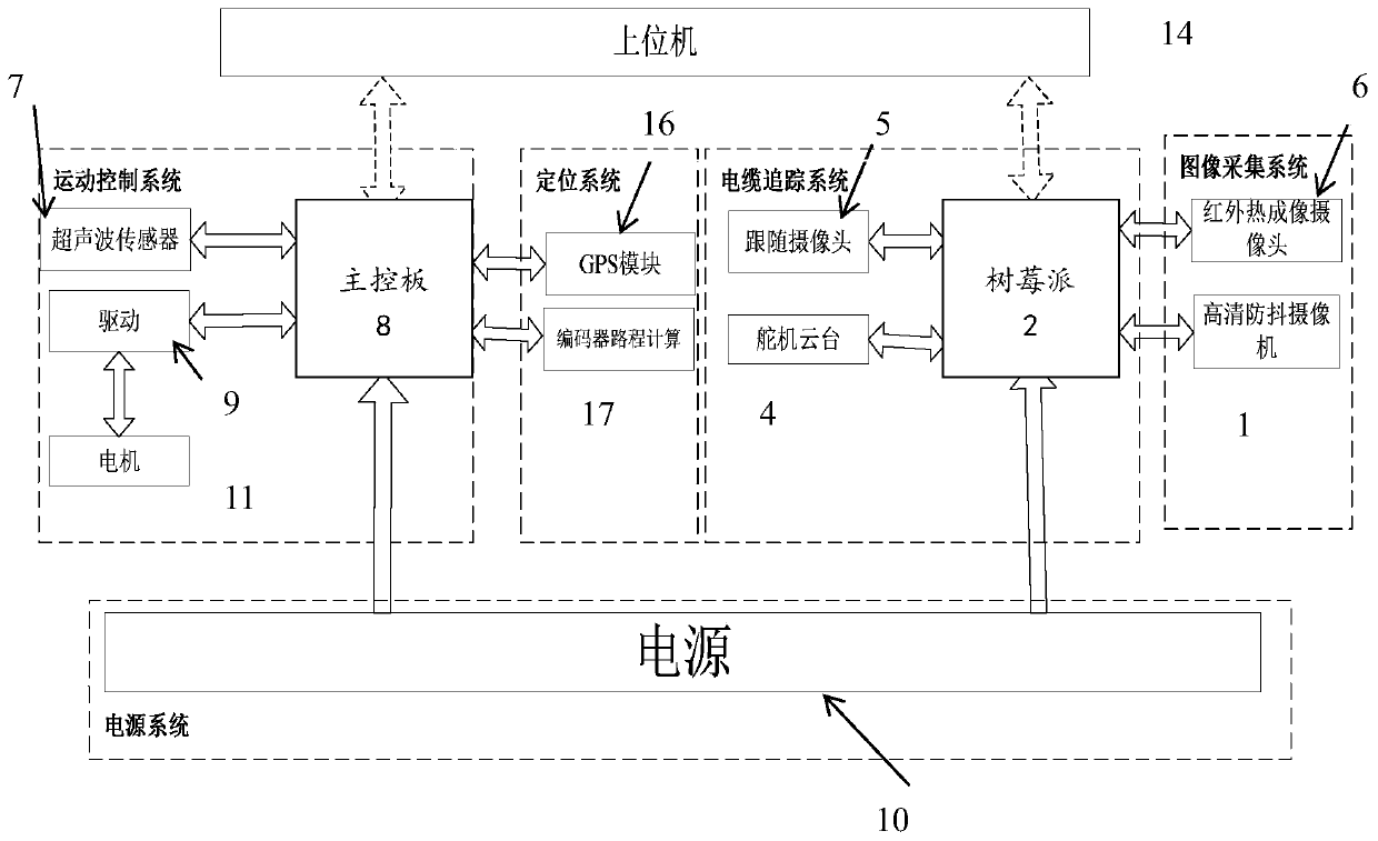
[0017] Such as Figure 1-Figure 3 As shown, the portable cable flaw detection robot system provided by the present invention includes a high-definition anti-shake camera 1, a raspberry pie 2, an LED light 3, a steering gear pan / tilt 4, a following camera 5, an infrared thermal imaging camera 6, an ultrasonic sensor 7, a main controller Plate 8, motor drive plate 9, power supply 10, motor 11, car body 12, support platform 13, GPS module 16 and distance calculation module 17; Wherein car body 12 adopts crawler structure; The lower end of support platform 13 is fixed on car body 12 edge of the top surface; HD anti-shake camera 1, raspberry pie 2, LED light 3 and steering gear pan / tilt 4 are installed on the top surface of support platform 13; following camera 5 and infrared thermal imagi...


PUM


Abstract

The invention provides a portable cable flaw detection robot system. The portable cable flaw detection robot system comprises a high-definition anti-shake camera, a raspberry part, an LED light, a steering gear cloud platform, a follow camera, an infrared thermal imaging camera, an ultrasonic sensor, a main control panel, a motor drive panel, a power supply, a motor, a trolley body, a support platform, a GPS module and a journey calculation module. the portable cable flaw detection robot system provided by the invention has the following beneficial effects that the portable cable flaw detection robot system has the characteristics of convenience and flexibility, can replace manual inspection, meets the requirements of a large number of daily cable inspection work for substation cable trenches, improves the work efficiency, saves a lot of manpower and material resources, lowers the operating cost, simultaneously greatly guarantees the reliability of the power supply of the substation, and provides a good foundation for big data analysis of the later cable operation management of the substation.

Description

technical field [0001] The invention belongs to the technical field of robot structures, in particular to a portable cable flaw detection robot system. Background technique [0002] At present, the cable fault detection technology at home and abroad can be roughly divided into two methods: online detection and offline detection. Off-line detection is to withdraw the power cable from the running state, and then use various offline monitoring methods such as bridge method, DC flashover method, pulse injection method, etc. To analyze the condition of the cable, but the off-line detection method needs several hours of power failure, so this method is not suitable for daily detection method under the current social situation that requires more and more reliability of electricity consumption. The online detection method is live detection, which can realize the monitoring of the cable status in the actual operating environment without the need for a power outage. Among them, the ca...

Claims


Application Information

Patent Timeline
Patent Type & Authority Applications(China)
IPC IPC(8): B25J11/00B25J19/02G01R31/08G01J5/00G01S15/931
CPCB25J11/00B25J19/023B25J19/02G01R31/083G01J5/0096G01S15/931G01J2005/0077
Inventor 赵迎春李想薛鸿昊夏棚李恒朝苗原荣黄哲
Owner CIVIL AVIATION UNIV OF CHINA
Why Eureka
Try Eureka