Turbine blade cooling structure adapted to integrated printing and molding and engine

A technology for turbine blades and cooling structures, applied in the direction of engine components, machines/engines, blade support components, etc., can solve problems such as reduced component life, large wake areas, and reduced air volume at the head of the combustion chamber, achieving short design cycles , cheap price, and the effect of reducing design cost

Pending Publication Date: 2020-07-17
INST OF ENGINEERING THERMOPHYSICS - CHINESE ACAD OF SCI
View PDF0 Cites 3 Cited by
  • Summary
  • Abstract
  • Description
  • Claims
  • Application Information

AI Technical Summary

Problems solved by technology

The cold air is drawn from the compressor, and the flow rate of the flow affects the turbine in the following ways: 1. If the turbine uses too much cold air flow, the air volume at the head of the combustion chamber will decrease, and the nitrogen oxide pollution in the combustion chamber will increase under the same power
2. If the turbine uses too much cold air flow, the trailing edge of the turbine blades will be thickened, resulting in a large wake area and reducing the aerodynamic efficiency
3. The cooling air flow is not enough to cool the turbine, which will reduce the life of t

Method used


Image

  • Turbine blade cooling structure adapted to integrated printing and molding and engine
  • Turbine blade cooling structure adapted to integrated printing and molding and engine
  • Turbine blade cooling structure adapted to integrated printing and molding and engine

Examples


Embodiment 1

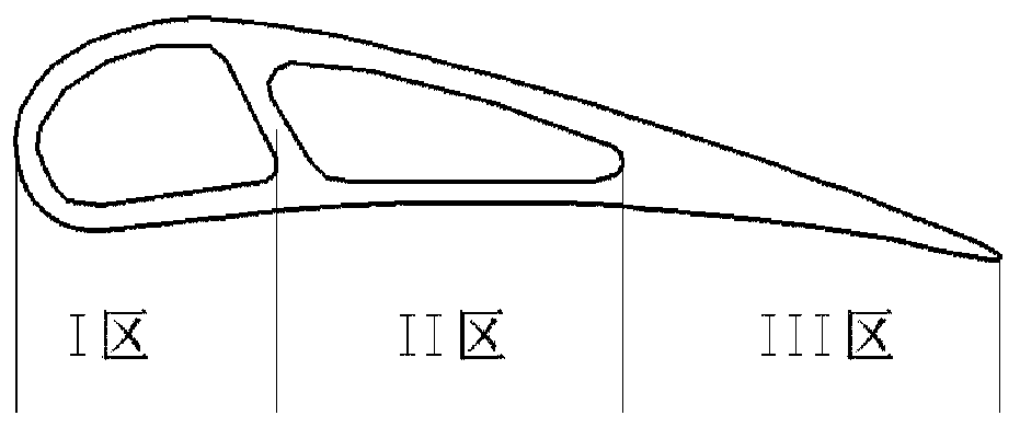
[0072] A turbine blade cooling structure suitable for integral printing and forming, which is a 3D printed gas turbine cooling blade, suitable for the first-stage guide vane of a 50MW gas turbine, the inlet temperature of the turbine is 1500K in the ISO state, and the TCLA flow rate is lower than 15%.

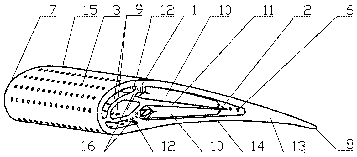
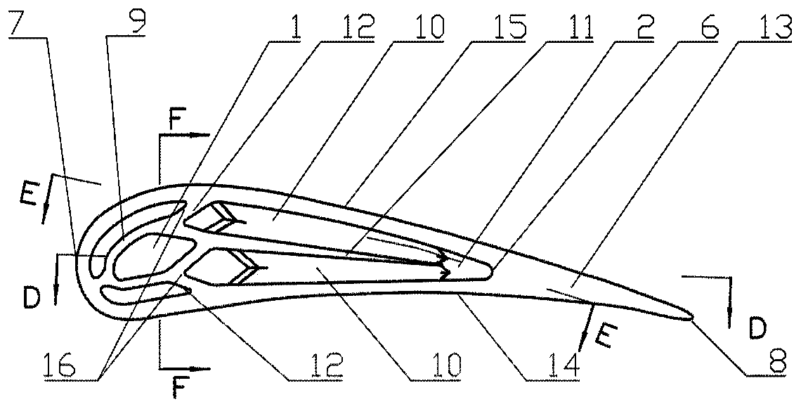
[0073] In the turbine blade cooling structure adapted to integral printing and forming of the present invention, the diameter of the air film hole 3 is 0.5 mm;

[0074] The impact cooling plate 9 is drop-shaped, and the diameter of the impact cooling holes on the impact cooling plate 9 is 1 mm;

[0075] The pressure surface 14 and the suction surface 15 of the second cooling zone 2 are respectively independent double-layer inclined matrix ribs 10, and a matrix rib support plate 11 is added between two sets of inclined matrix ribs 10; the single rib width of the inclined matrix ribs 10 is 1.5mm, The rib spacing is 3.5mm, and the rib height decreases continuously along the chord ...


PUM

PropertyMeasurementUnit
Apertureaaaaaaaaaa

Abstract

The invention discloses a turbine blade cooling structure adapted to integrated printing and molding and an engine. The turbine blade cooling structure adapted to integrated printing and molding includes a leading edge, a trailing edge, a pressure surface and a suction surface of a turbine blade; the blade is defined to be a first cooling zone, a second cooling zone and a third cooling zone in sequence from the leading edge to the trailing edge; the first cooling zone includes air film holes and a closed impingement cooling plate; the air film holes are arranged on the front edge of the firstcooling zone; the impingement cooling plate is arranged inside the first cooling zone, and the impingement cooling plate is provided with impingement cooling holes; the second cooling zone includes two sets of inclined matrix ribs and matrix rib support plates; and the third cooling zone includes seam splitting grooves. The invention adopts a cooling structure combined with three cooling zones, which not only improves the cooling effect, but also meets the requirements of integrated printing and molding.

Description

technical field [0001] The invention relates to the field of turbine blade structure design and preparation, in particular to a turbine blade cooling structure and engine adapted to integrated printing and forming. Background technique [0002] The efficiency and power of modern gas turbines have increased with increasing turbine inlet temperatures. Turbine buckets and vanes are exposed to high temperatures that exceed the melting point of metallic compounds. Therefore an internal cooling structure is required. For turbine blade cooling structures, it is important to use appropriate boundary conditions and to have a sound mechanical design to avoid excessive temperature gradients. Because excessive temperature gradients will lead to increased thermal stress and reduce component life. [0003] Internal cooling and external cooling are two important cooling methods for turbine blades. The cold air is drawn from the compressor, and the flow rate of the flow affects the turb...

Claims


Application Information

Patent Timeline
IPC IPC(8): F01D5/18
CPCF01D5/18F01D5/186
Inventor 杨旸余志健付经伦
Owner INST OF ENGINEERING THERMOPHYSICS - CHINESE ACAD OF SCI
Why Eureka
Try Eureka