Method for determining position of fixation point in three-dimensional scene by adopting scanner and eye tracker

A technology of 3D scenes and scanners, which is applied in the field of solving the calculation of gaze point position in 3D space, and achieves the effect of avoiding the problem of missing solutions

Active Publication Date: 2020-07-17
中国人民解放军海军特色医学中心
View PDF5 Cites 8 Cited by
  • Summary
  • Abstract
  • Description
  • Claims
  • Application Information

AI Technical Summary

Problems solved by technology

This method leads to the need to face a huge amount of eye movement data in the follow-up analysis; the position of the telemetry single camera eye tracker and the plane scene is relatively fixed, and the establishment of the scene model is completed through the calibration process, that is, the calibration of the eye tracker , The relative positional relationship between the observed object and the test object, and established a coordinate system based on the eye tracker

Method used


Image

  • Method for determining position of fixation point in three-dimensional scene by adopting scanner and eye tracker
  • Method for determining position of fixation point in three-dimensional scene by adopting scanner and eye tracker
  • Method for determining position of fixation point in three-dimensional scene by adopting scanner and eye tracker

Examples


Embodiment Construction

[0054] Example embodiments will now be described more fully with reference to the accompanying drawings. Example embodiments may, however, be embodied in many forms and should not be construed as limited to the examples set forth herein; rather, these embodiments are provided so that this disclosure will be thorough and complete and fully convey the concept of example embodiments to those skilled in the art. The described features, structures, or characteristics may be combined in any suitable manner in one or more embodiments. In the following description, numerous specific details are provided in order to give a thorough understanding of embodiments of the invention. However, those skilled in the art will appreciate that the technical solution of the present invention may be practiced without one or more of the specific details, or other methods, components, devices, steps, etc. may be adopted. In other instances, well-known technical solutions have not been shown or descr...


PUM


Abstract

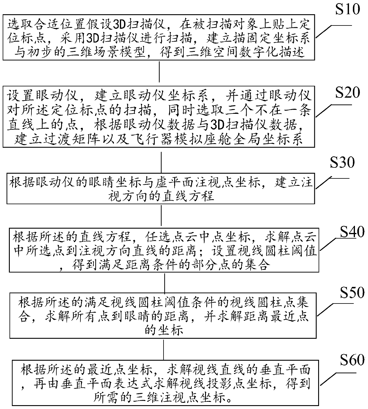
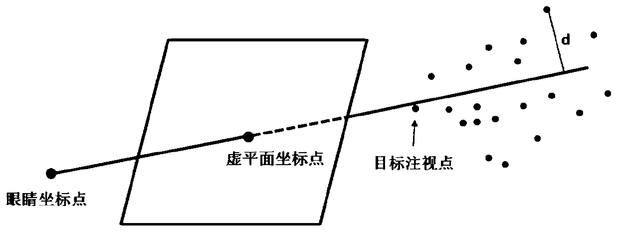
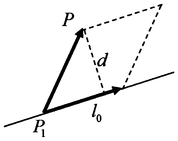
The invention discloses a method for determining the position of a fixation point in a three-dimensional scene by adopting a scanner and an eye tracker, and belongs to the technical field of eye movement tracking. Three-dimensional scanning and modeling are carried out on a three-dimensional scene through a 3D scanner, then three non-collinear points are positioned through an eye tracker, and thecoordinate conversion relation between the eye tracker and the scanner is established. Establishing a gaze linear equation according to the virtual plane gaze point coordinates of the eye tracker andthe eye coordinates; a sight point set is obtained by setting a cylindrical threshold value, a fixation point is searched out by minimizing the distance between the sight point set and the eyes, moreaccurate three-dimensional fixation point coordinates are further solved by solving a fixation straight line vertical plane method, and an analytical expression of the coordinates is given, so that accurate and quick tracking of a three-dimensional scene of eye fixation is realized. According to the method, the defects of complex calculation and huge calculated amount of a traditional method are avoided.

Description

technical field [0001] The present invention relates to the technical field of eye movement tracking, in particular to a calculation method for solving gaze point positions in three-dimensional space. Background technique [0002] Eye tracking technology, also known as eye tracking technology, is currently mainly used in web page layout optimization, scene research, human-computer interaction, virtual reality, clinical medicine and other fields. Gaze tracking currently relies on eye tracker equipment to achieve. There are currently two types of eye trackers on the market: head-mounted and telemetry eye trackers. The head-mounted eye tracker needs to wear a helmet on the head or wear glasses on the eyes, which adds a certain burden to the subjects. The telemetry eye tracker does not need to wear any device for the subjects, which has little interference to the subjects, and can detect the eye movement data of the natural state of the subjects. [0003] The most critical te...

Claims


Application Information

Patent Timeline
Patent Type & Authority Applications(China)
IPC IPC(8): G06F3/01G06T7/73
CPCG06F3/013G06T7/73G06T2207/10028
Inventor 王庆敏李科华姚永杰时粉周
Owner 中国人民解放军海军特色医学中心
Why Eureka
Try Eureka