Optical communication MIMO detection method and system

A detection method and optical communication technology, applied in the field of optical communication, can solve problems such as small number of mode inputs and outputs, complex algorithms, difficult implementation, etc., to achieve the effects of avoiding time, good detection effect, and improving structural efficiency

Active Publication Date: 2020-07-17
DONGGUAN POLYTECHNIC
View PDF12 Cites 5 Cited by
  • Summary
  • Abstract
  • Description
  • Claims
  • Application Information

AI Technical Summary

Problems solved by technology

However, the algorithm of the prior art 3 is relatively complex and difficult to implement. Although the deep learning t

Method used


Image

  • Optical communication MIMO detection method and system
  • Optical communication MIMO detection method and system
  • Optical communication MIMO detection method and system

Examples


Embodiment 1

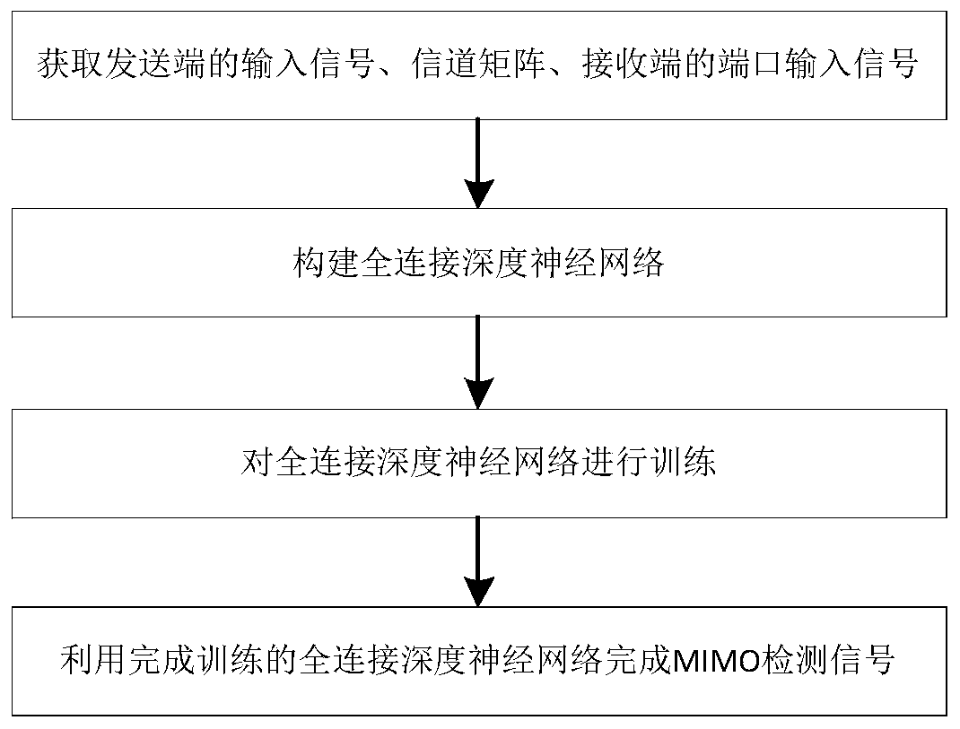
[0041] A kind of optical communication MIMO detection method, described detection method comprises the following steps:

[0042] S1: Obtain the input signal d(t) at the sending end of the optical communication system, the channel matrix H, and the port output R at the receiving end x (t)=[r x1 (t), r x2 (t),...,r xN (t)] T ∈C N ;

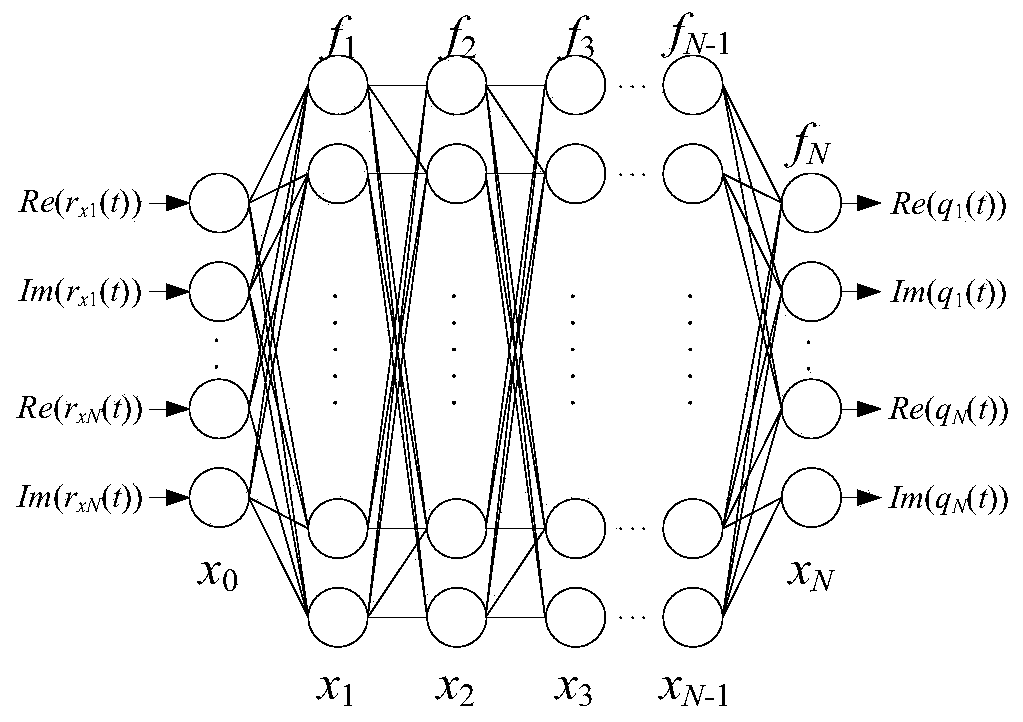
[0043]S2: Construct a fully connected deep neural network with M layers, the structure of the fully connected deep neural network is as follows figure 2 As shown, expressed as a mapping function f(x 0 ;θ): R D0 →R DM , after M iterations the input vector x 0 ∈ R D0 transform to output vector x M ∈ R DM , where x 0 =[Re(r x1 (t)), Im(r x1 (t)), Re(r x2 (t)), Im(r x2 (t)),..., Re(r xN (t)), Im(r xN (t))], the iterative process is defined as:

[0044] x m = f m (x m-1 ; θ m )

[0045] Where: x m = f m (x m-1 ; θ m ) means R Dm-1 →R Dm is the mapping function of the Mth layer, θ m is the parameter of the neural network, ...

Embodiment 2

[0094] Such as Figure 4 As shown, an optical communication MIMO system includes a transmitting end, a receiving end, and a multimode optical fiber connecting the transmitting end and the receiving end,

[0095] The sender includes

[0096] A subcarrier multiplexing module with N quadrature phase shift keying modulators (Quadrature Phase Shift Keying, QPSK), the subcarrier multiplexing module is used to receive input signals, and the quadrature phase shift keying The load wave frequency of the modulator is set to f c .

[0097] TX with Mach-Zehnder Modulator (MZM) and Optical Carrier Amplifier i The module is used to control the Mach-Zehnder optical modulator through the modulation symbol of the quadrature phase shift keying modulator, so as to realize the adjustment of the intensity of the optical signal;

[0098] assuming d in is the nth input bit of the ith channel. The output of the i-th QPSK modulator is:

[0099]

[0100] Where: f c is the load wave frequency,...


PUM


Abstract

The invention discloses an optical communication MIMO detection method and system. The detection method comprises the following steps: acquiring an input signal d(t) and a channel matrix H of a transmitting end of an optical communication system, and a port output Rx(t) of a receiving end; constructing an M-layer full-connection deep neural network which is expressed as a mapping function f(x0;theta):RD0->RDM, and converting an input vector x0 belonging to RD0 into an output vector xM belonging to RDM through M times of iteration; training the full-connection deep neural network by adopting different CN data; in the training process, a first-order optimization algorithm is adopted for gradient calculation based on a cost function, a parameter theta is dynamically updated, an expected valueof J(theta) is minimized, an input signal d(t) belonging to BN is trained in step S3 to obtain the fully connected deep neural network output d'(t) belonging to BN, which completes the detection of the MIMO signal. The present invention adopts the first-order optimization algorithm based on the gradient calculation of the cost function to realize the training of the deep neural network, and the nonlinear coupling problem of multimode optical communication is solved by using the strong nonlinear learning ability of the deep neural network.

Description

technical field [0001] The present invention relates to the technical field of optical communication, and more specifically, to an optical communication MIMO detection method and system. Background technique [0002] Traditional technologies such as time division multiplexing, wavelength division multiplexing and polarization multiplexing have successfully improved the channel utilization and transmission efficiency of optical communication systems. With the development of communication technology, the mode division multiplexing (Mode Division Multiplexing, MDM) technology has further improved the channel utilization of optical communication. A multiple output (Multiple Input Multiple Output, MIMO) technology can effectively improve the performance of an optical communication system. Although multimode transmission improves the efficiency and speed of optical communication, nonlinear coupling occurs within each mode and between multiple modes during optical transmission. T...

Claims


Application Information

Patent Timeline
IPC IPC(8): H04B7/0413H04B10/25H04B10/556H04J14/02
CPCH04B7/0413H04B10/25H04B10/556H04J14/0202H04J14/0227
Inventor 杨恺王军赵美玲杨润丰麦强陈晓宁司马嘉欣
Owner DONGGUAN POLYTECHNIC
Why Eureka
Try Eureka