Dual-layer dual-spiral cooling hot blast valve plate and work method thereof

A double helix, hot blast valve technology, applied in blast furnace parts, furnaces, heating furnaces, etc., can solve the problems of large heat loss, fatigue cracking of welding joints, etc., achieve small heat loss, overcome large cooling water consumption, and reduce heat The effect of passing

Pending Publication Date: 2020-07-24
XIAMEN UNIV TAN KAH KEE COLLEGE
0 Cites 0 Cited by

AI-Extracted Technical Summary

Problems solved by technology

In practical application, since the sealing surface is an integral forged piece, it has a welded structure, the double-sided sealing surface, and the sealing ring of the entire valve plate leaks out of the fire-resistant and heat-insulatin...

Method used

A kind of working method of double-layer double-helix cooling hot air valve valve plate, carries out as follows: cooling water flows in from water inlet, flows through the outer ring waterway of upper strata waterway, valve plate outer water ring and sealing surface are cooled , and then enter the double helix cooling water channel of the upper water channel through the set diversion hole, flow to the middle connecting shaft and enter the double helix cooling water channel of the lower water channel, flow through the double helix cooling water channel of the lower water channel and the outer ring water channe...

Abstract

The invention relates to a dual-layer dual-spiral cooling hot blast valve plate. The dual-layer dual-spiral cooling hot blast valve plate comprises a valve plate body. The interior of the valve platebody is divided into an upper-layer water channel and a lower-layer water channel which are adjacent to each other through an interlayer plate. The upper-layer water channel communicates with the lower-layer water channel through communication shafts, and the upper-layer water channel and the lower-layer water channel each comprise an outer water ring, an inner enclosure plate, a dual-spiral cooling water channel and a communication shaft from outside to inside in sequence. An outer ring water channel is formed between the outer water ring and the inner enclosure plate of the same layer, the outer ring water channel and the outer end of the dual-spiral cooling water channel of the same layer communicate with each other through a flow diversion hole, and the inner ends of the dual-spiral cooling water channels communicate with the communication shafts. A water inlet is connected to the outer ring water channel of the upper-layer water channel, a water outlet is connected with the outerring water channel of the lower-layer water channel, and the outer ring water channel between the water inlet and the flow diversion hole of the same layer and the outer ring water channel between thewater outlet and the flow diversion hole of the same layer are provided with water fenders. The dual-layer dual-spiral cooling hot blast valve plate overcomes the defects of large consumption amountof cooling water and low cooling efficiency in the prior art, the quality of a hot blast valve is greatly improved, and the service life of the hot blast valve is greatly prolonged.

Application Domain

Blast furnace detailsHeating stoves

Technology Topic

Hot blastEngineering +4

Image

  • Dual-layer dual-spiral cooling hot blast valve plate and work method thereof
  • Dual-layer dual-spiral cooling hot blast valve plate and work method thereof
  • Dual-layer dual-spiral cooling hot blast valve plate and work method thereof

Examples

  • Experimental program(1)

Example Embodiment

[0016] In order to make the above-mentioned features and advantages of the present invention more comprehensible, the following specific examples are given in conjunction with the drawings, and detailed descriptions are made as follows.
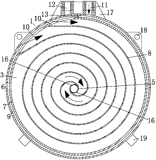
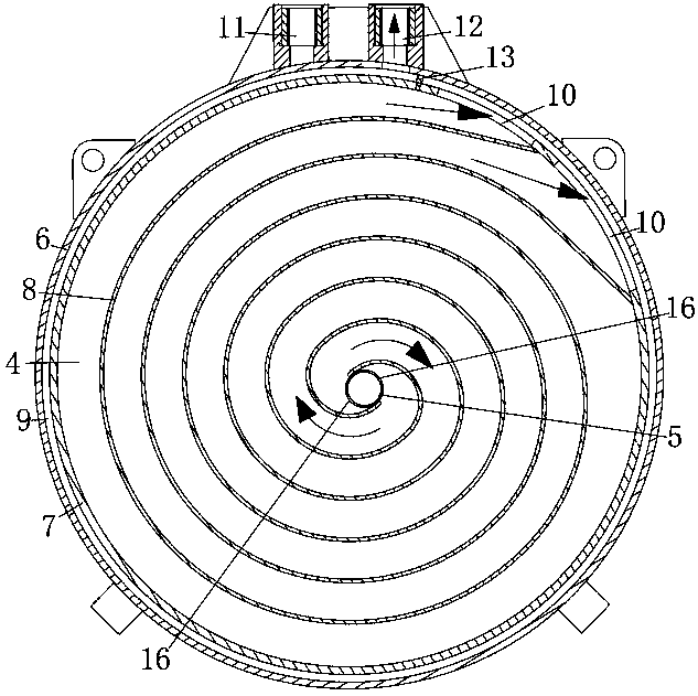
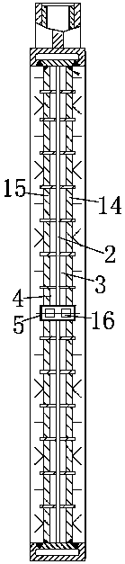
[0017] Such as Figure 1~3 As shown, a double-layer double spiral cooling hot air valve valve plate includes a valve plate body 1, which is separated from adjacent upper water channels 3 and lower water channels 4 by a partition plate 2, between the upper water channel and the lower water channel Connected by the connecting shaft 5, the upper water channel and the lower water channel include the outer water ring 6, the inner wall 7, the double spiral cooling water channel 8, and the connecting shaft from the outside to the inside. Among them: the outer water ring and the inner wall of the same layer The outer ring water channel 9 is formed between the outer ring water channel of the same layer and the outer end of the double spiral cooling water channel are connected through the guide hole 10, and the inner end of the double spiral cooling water channel is connected with the connecting shaft; the outer ring water channel of the upper water channel is connected into Water outlet 11, the outer ring waterway of the lower waterway is connected to the water outlet 12, the outer ring waterway between the water inlet and the diversion hole of the same layer, and the outer ring waterway between the water outlet and the diversion hole of the same layer are equipped with water blocking Board 13.
[0018] In the embodiment of the present invention, the end surface of the upper water channel seals the outer ring water channel and the end surface of the double spiral cooling water channel via the upper cover plate 14, and the end surface of the lower water channel seals the outer ring water channel and the end surface of the double spiral cooling water channel via the lower cover plate 15.
[0019] In the embodiment of the present invention, the double spiral cooling water channels are spirally connected from the guide hole to the connecting shaft from the outside to the inside, and the double spiral cooling water channels of the same layer all share the same adjacent side.
[0020] In the embodiment of the present invention, the two ends of the communicating shaft are closed, and both ends of the communicating shaft are provided with ports 16 communicating with the inner ends of the double spiral cooling water channels of the same layer.
[0021] In the embodiment of the present invention, the outer periphery of the water inlet and the water outlet are fixedly provided with ribs 17 integrally connected with the valve plate body.
[0022] In the embodiment of the present invention, a plurality of lifting lugs 18 and supports 19 are fixedly provided on the outer periphery of the valve plate body.
[0023] A working method of double-layer double spiral cooling hot air valve valve plate is carried out as follows: cooling water flows in from the water inlet, flows through the outer ring water channel of the upper water channel, cools the outer water ring and sealing surface of the valve plate, and then passes through The set diversion hole enters the double spiral cooling water channel of the upper water channel, flows to the double spiral cooling water channel of the middle connecting shaft into the lower water channel, flows from the inside to the outside through the double spiral cooling water channel of the lower water channel and the outer ring water channel, and finally discharges from the water outlet; The use of a brand-new water channel circulation structure, the outer water ring and important parts of the sealing surface are first cooled, and the valve plate body adopts a double-layer double helix, first from the outside to the inside, then from the top to the bottom, and then from the inside to the outside, effectively reducing It improves the heat transfer, overcomes the disadvantages of large amount of cooling water and low cooling efficiency, and greatly improves the quality and service life of the hot air valve.

PUM

no PUM

Description & Claims & Application Information

We can also present the details of the Description, Claims and Application information to help users get a comprehensive understanding of the technical details of the patent, such as background art, summary of invention, brief description of drawings, description of embodiments, and other original content. On the other hand, users can also determine the specific scope of protection of the technology through the list of claims; as well as understand the changes in the life cycle of the technology with the presentation of the patent timeline. Login to view more.

Similar technology patents

Bakelite poured mould

InactiveCN106426692Areduce heat transferprevent curing
Owner:绵阳市兴和模具有限公司

Classification and recommendation of technical efficacy words

  • reduce heat transfer
  • Improve quality and service life

Passively controlled smart microjet cooling array

ActiveUS20140204532A1reduce heat transferhigh spatial resolution
Owner:PARKER INTANGIBLES LLC

Steel stud with openings and edge formations and method for making such a steel stud

InactiveUS20050229523A1reduce heat transfer characteristicreduce heat transfer
Owner:BODNAR ERNEST R

Multifunctional grain depot ventilating device

InactiveCN102870555AReduce grain storage lossesreduce heat transfer
Owner:天津市滨海新区滨粮粮食购销有限公司

Method for whitening tourmaline powder by using hydrothermal method

InactiveCN103803569AImprove quality and service life
Owner:厦门山俊水杰科技有限公司

Method for preventing automobile bumper surface from blister

InactiveCN103286943Areduce foamingImprove quality and service life
Owner:HEFEI CHANGAN AUTOMOBILE

Production method of roll-bond evaporator for new energy equipment

PendingCN114346626AImprove quality and service life
Owner:CHANGZHOU CHANGZHENG EVAPORATOR

A method for improving mould resistance and ageing resistance of plaited bamboo products

InactiveCN107309746AImprove mold resistance and anti-aging abilityImprove quality and service life
Owner:阜南县柳祥工艺品有限公司

Sewing machine

ActiveCN108193394AImprove quality and service lifesmall structural changes
Owner:JACK SEWING MASCH CO LTD
Why Eureka
Try Eureka