High-steep terrain bridge-tunnel connecting digging-after-filling foam concrete transition structure and construction method

A technology of foam concrete and transitional structure, which is applied in foundation structure engineering, excavation, earthwork drilling and mining, etc. It can solve the problems of large bridge piles, cracks at the joints, and bridge pile deviations, etc., and achieves good strength and overall rigidity. The effect of small footprint and small foundation settlement

Pending Publication Date: 2020-07-24
ZHEJIANG UNIV CITY COLLEGE
View PDF0 Cites 2 Cited by
  • Summary
  • Abstract
  • Description
  • Claims
  • Application Information

AI Technical Summary

Problems solved by technology

In this way, the high fill in the joint section of the bridge head is likely to exert a large horizontal soil pressure on the bridge piles, resulting in deflection or instability of the bridge piles, and the uneven settlement is likely to cause cracks at the joints or excessive settlement differences.
Moreover, the geology at the entrance of the tunnel with high and steep terrain is unstable, and the excavation of the entrance and the construction of the tunnel entrance are likely to cause collapse at the entrance
In addition, the construction of bridge piles, caps, and columns on high and steep terrain lacks a sufficiently flat and stable construction site.

Method used


Image

  • High-steep terrain bridge-tunnel connecting digging-after-filling foam concrete transition structure and construction method
  • High-steep terrain bridge-tunnel connecting digging-after-filling foam concrete transition structure and construction method

Examples


Embodiment Construction

[0040] The present invention will be further described below in conjunction with the examples. The description of the following examples is provided only to aid the understanding of the present invention. It should be pointed out that for those skilled in the art, without departing from the principles of the present invention, some improvements and modifications can be made to the present invention, and these improvements and modifications also fall within the protection scope of the claims of the present invention.

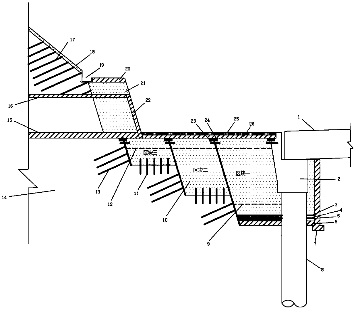
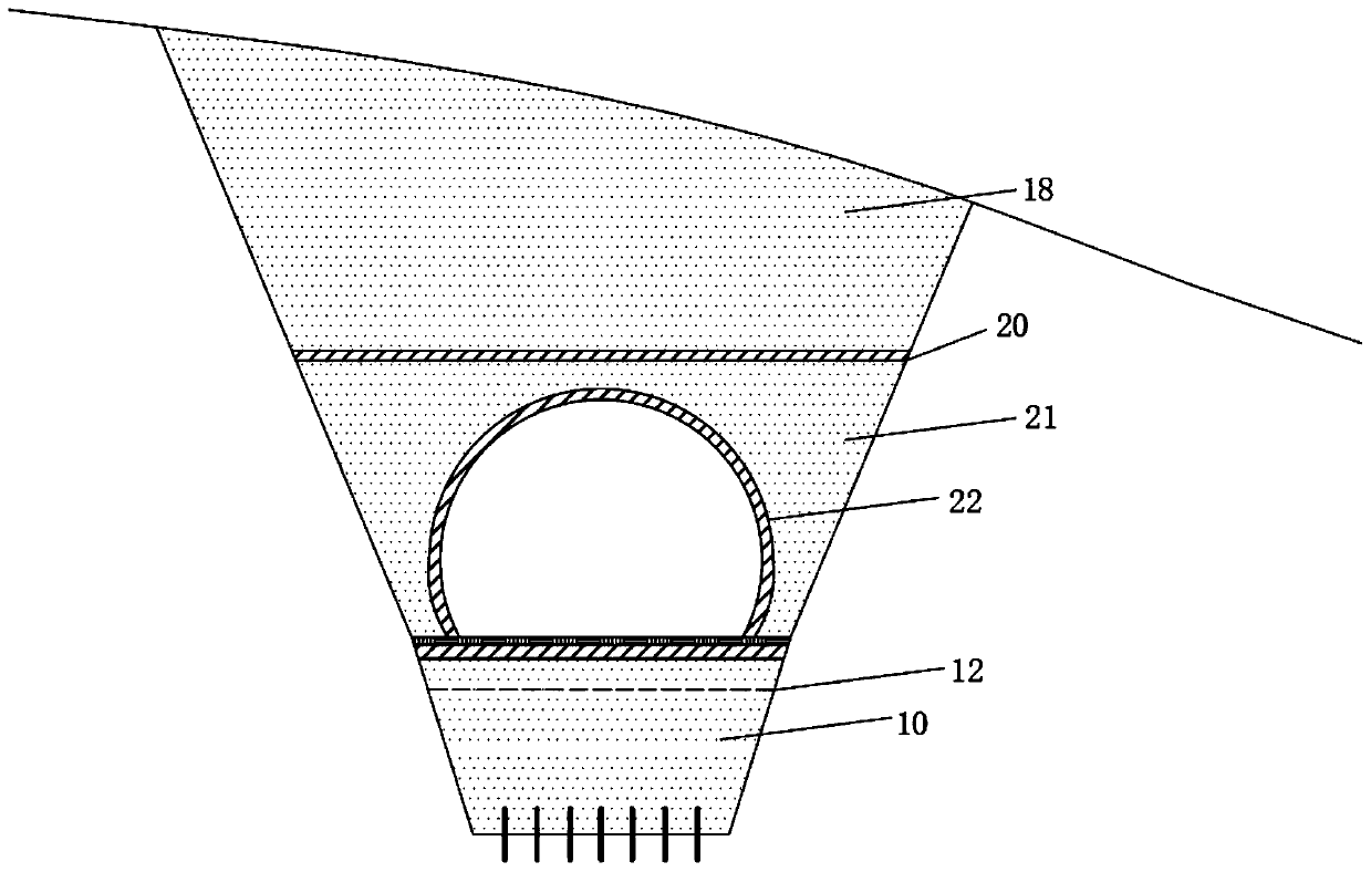
[0041]The bridge-tunnel connection in the high and steep terrain is filled first and then excavated with a foam concrete transition structure. The transition section between the abutment 2 and the tunnel opening is provided with a foam concrete embankment 10. The foam concrete embankment is light in weight, has small foundation settlement, and has good strength and overall rigidity. , the transition from the tunnel to the bridge 1 through the foam concrete embank...


PUM


Abstract

The invention relates to a high-steep terrain bridge-tunnel connecting digging-after-filling foam concrete transition structure. The high-steep terrain bridge-tunnel connecting digging-after-filling foam concrete transition structure comprises a bridge abutment, a bridge pile, a foam concrete embankment, recycling anchor rods, a tunnel bottom plate, a tunnel lining, glass fiber reinforced plasticanchor rods, reinforced concrete chipping table, a foam concrete filling body, a reinforced concrete portal, a bituminous pavement and a reinforced concrete plate. The foam concrete embankment is mounted on a transition segment between the bridge abutment and a tunnel portal, steps are mounted on a foundation on the bottom of the foam concrete embankment, slopes are mounted on two sides of the steps and the foam concrete embankment, the recycling anchor rods are mounted in slope surface foundations of the step slopes, anti-sliding anchor nails are mounted on the bottoms of the steps, and the structure has the beneficial effects that the foam concrete embankment is mounted on the transition segment between the bridge abutment and the tunnel portal, the foam concrete embankment is small in mass, small in foundation settlement and meanwhile, good in strength and whole rigidity, the elasticity modulus of foam concrete is close to a tunnel and a bridge, and transition from the tunnel to thebridge is uniform through the foam concrete embankment

Description

technical field [0001] The invention relates to a bridge-tunnel connection transition structure, in particular to a bridge-tunnel connection bridge-tunnel connection structure with high and steep terrain and a construction method thereof. Background technique [0002] The ratio of bridges and tunnels is usually relatively high in highway construction projects with high and steep terrain, and there are many sections connected by short-circuit foundations between bridges and tunnels. The short-distance connection between the rigid road surface of the bridge-tunnel section and the flexible road surface of the soil section needs to achieve two transitions of rigidity and softness, and softness and rigidity. , the construction is difficult, and there are many hidden dangers in quality. The usual practice is to form a flexible short-circuit base with high fill in the transition section, and the transition between the subgrade, the bridge abutment and the tunnel entrance is through...

Claims


Application Information

Patent Timeline
Patent Type & Authority Applications(China)
IPC IPC(8): E21D9/14E21D11/10E21D20/02E21D21/00E21F15/00E21D11/38E01C3/04E01D19/02E02D5/74E02D17/20
CPCE01C3/04E01D19/02E02D5/74E02D17/20E21D9/14E21D11/10E21D11/38E21D20/02E21D21/0006E21F15/005
Inventor 王新泉崔允亮刁红国
Owner ZHEJIANG UNIV CITY COLLEGE
Why Eureka
Try Eureka