Gas water heater

A gas water heater, gas technology, applied in water heaters, fluid heaters, lighting and heating equipment, etc., can solve problems such as easy corrosion of walls

Inactive Publication Date: 2020-07-24
NINGBO FOTILE KITCHEN WARE CO LTD
View PDF6 Cites 5 Cited by
  • Summary
  • Abstract
  • Description
  • Claims
  • Application Information

AI Technical Summary

Problems solved by technology

[0003] The technical problem to be solved by the present invention is to provide a gas water heater to overcome the defect that the wall surface of the combustion chamber of the gas water heater is prone to corrosion in the prior art.

Method used


Image

  • Gas water heater
  • Gas water heater
  • Gas water heater

Examples


Embodiment 1

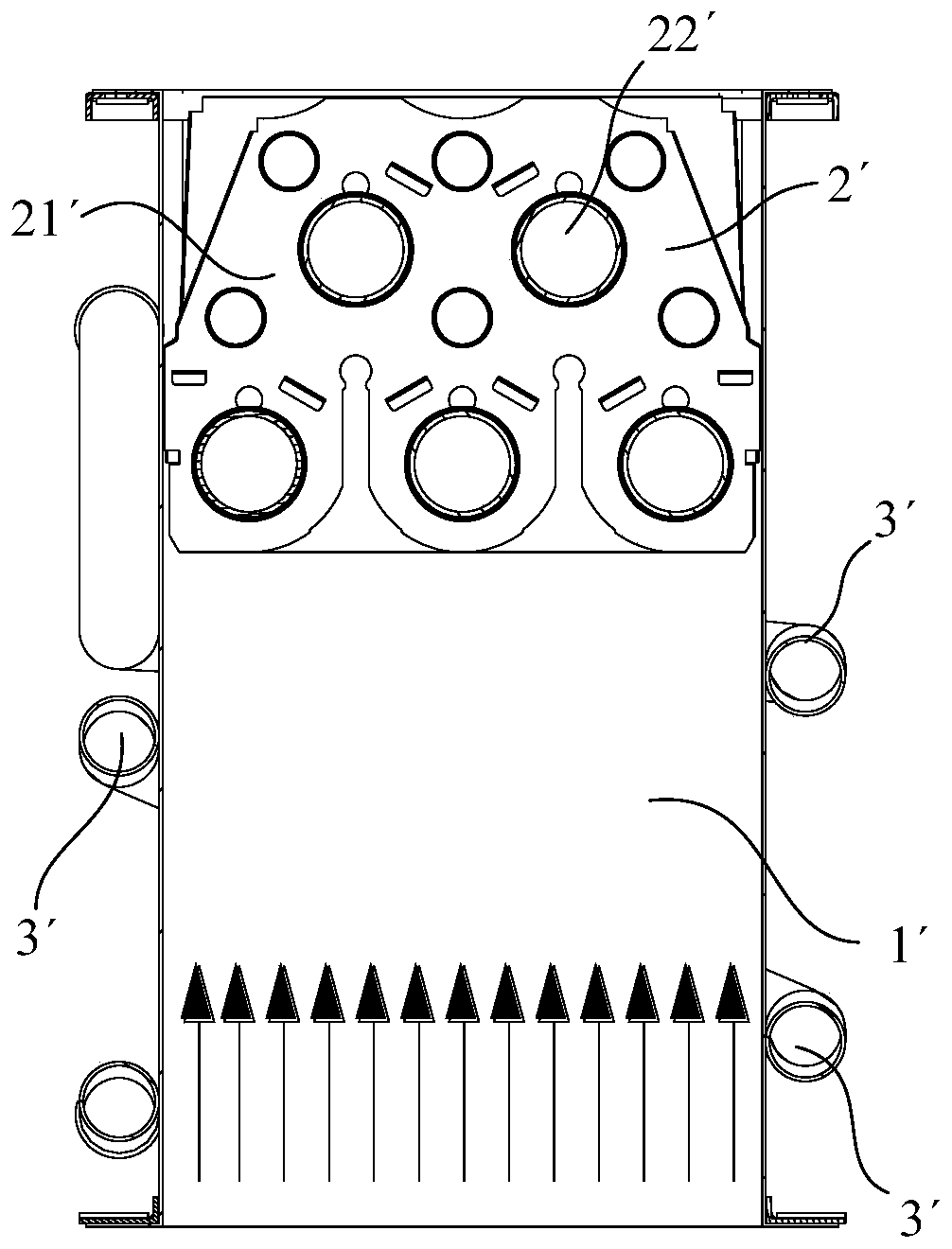
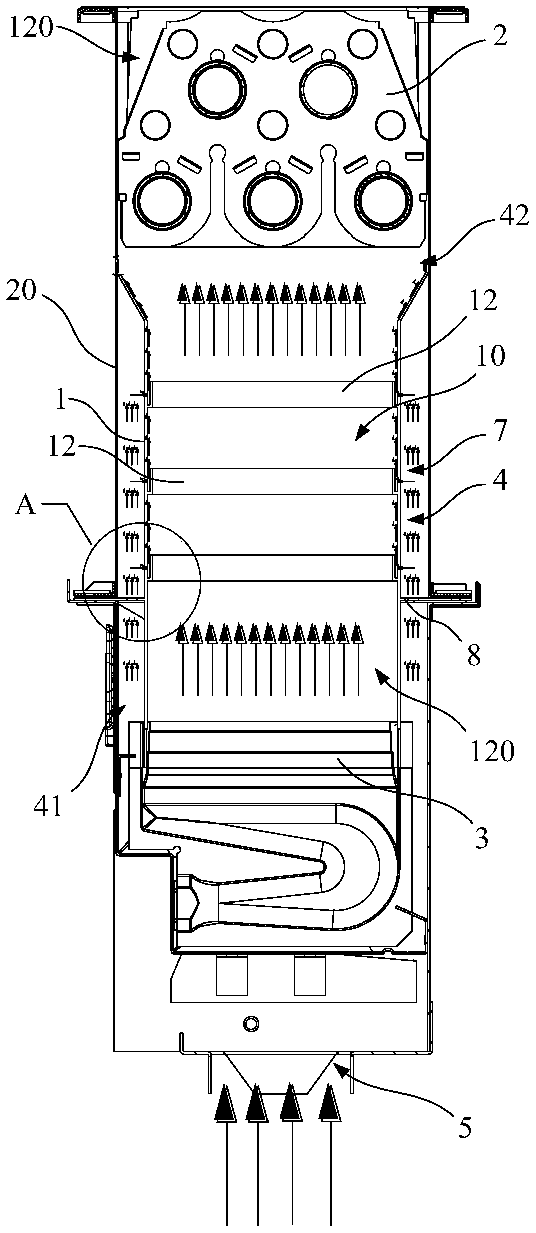
[0072] Figure 2 to Figure 5 Shown is the gas water heater of Embodiment 1 of the present invention. In this embodiment, the gas water heater includes a casing 1, a heat exchanger 2 and a burner 3, a combustion chamber 10 is formed in the casing 1, and the heat exchanger 2 is arranged in a heat exchange area 120 of the combustion chamber 10, The burner 3 is disposed in the combustion area 110 of the combustion chamber 10 . The mixture of gas and air is burned at the burner 3 , and the high-temperature flue gas generated flows to the heat exchange area 120 and exchanges heat with the heat exchanger 2 .

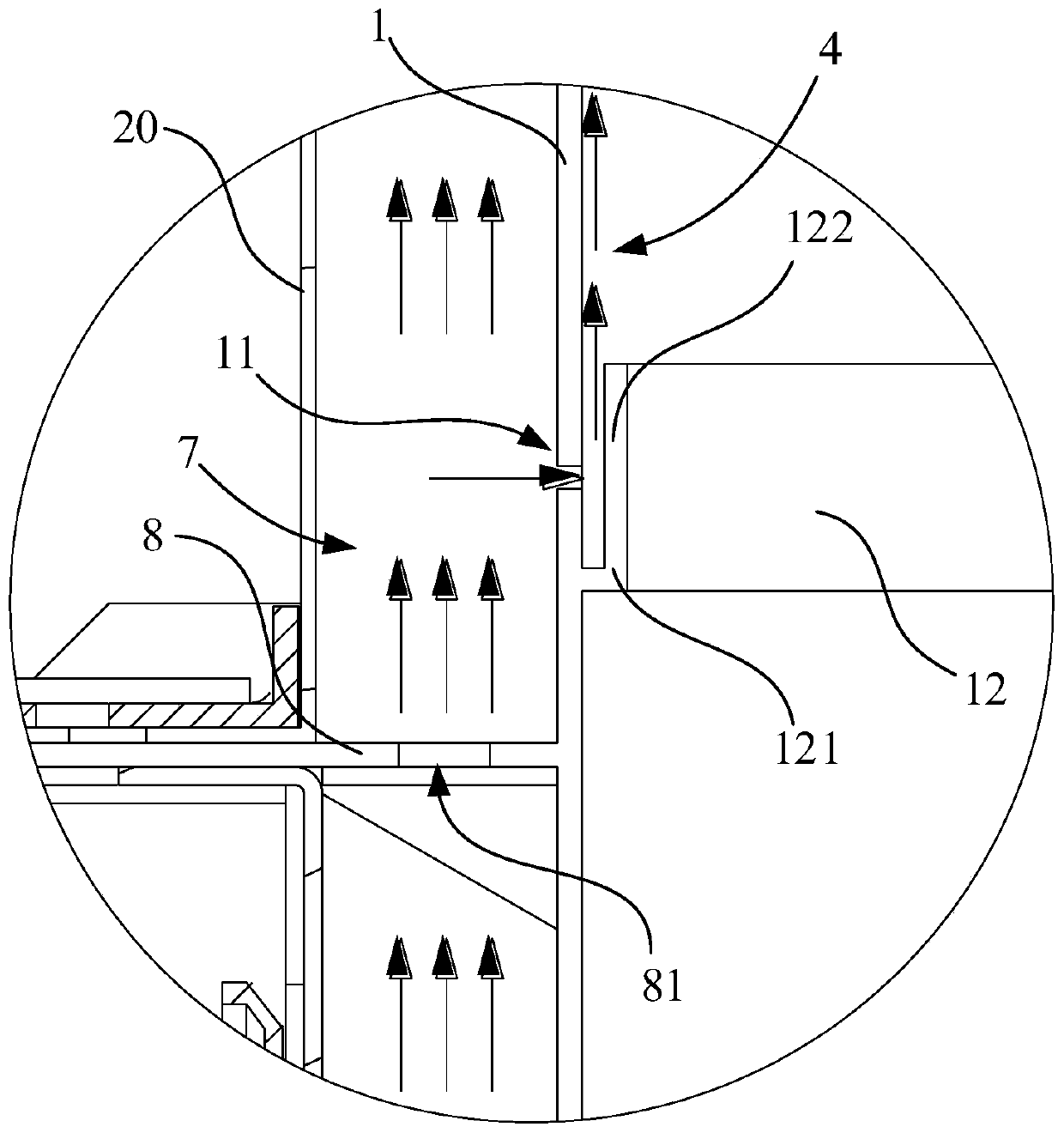
[0073] The gas water heater also includes an air film generating mechanism. The air film generating mechanism has an air flow path 4 flowing through the combustion chamber 10. The air flow path 4 is formed on the inner wall surface of the housing 1. The air film generating mechanism drives air to flow through the air flow path 4. The inside flows to the heat exchange area 120...

Embodiment 2

[0088] Such as Figure 6 and Figure 7 As shown, it is the gas water heater of embodiment 2 of the present invention, the gas water heater of embodiment 2 is basically the same as embodiment 1, the difference is: the fan 6 is arranged at the end 42 of the air flow path 4, and the fan 6 is an exhaust fan 6.

[0089] The exhaust fan 6 can extract air from the end 42 of the air flow passage 4 , so as to realize the function of driving air to flow in the air flow passage 4 . The end 42 of the air flow passage 4 coincides with the smoke exhaust passage of the heat exchange area 120, and the fan 6 is also used to drive the smoke to be discharged from the combustion chamber 10. While the fan 6 drives the air flow in the air flow passage 4, it also The driving flue gas is discharged from the combustion chamber 10, which can effectively reduce the number of components in the gas water heater.

[0090] In addition, in this embodiment, the gas water heater also includes a cooling wall...


PUM


Abstract

The invention discloses a gas water heater. The gas water heater comprises a shell, a heat exchanger and a burner, wherein a burning chamber is formed in the shell, the heat exchanger is located in aheat exchange region of the burning chamber, and the burner is located in the burning region of the burning chamber; a mixed gas of fuel gas and air burns in the burner, and generated high-temperaturesmoke flows to the heat exchange region; the gas water heater further comprises an air film generation mechanism, wherein the air film generation mechanism is provided with an air flowing passage which passes through the burning chamber, and the air flowing passage is formed in the surface of the inner wall of the shell; and the air film generation mechanism drives the air to form airflow in theair flowing passage, the airflow flows along the inner wall of the cooled shell to carry away heat of the shell, and meanwhile condensed water condensed on the inner wall of the shell also can be carried away. Since the flowing direction of the airflow in the air flowing passage is the same as the fuel gas flowing direction, the heated air finally can flow to the heat exchanger for heat exchange,and energy cannot be wasted.

Description

technical field [0001] The invention relates to the field of water heaters, in particular to a gas water heater. Background technique [0002] figure 1 It is a structure widely used in gas water heaters at present. The gas water heater has at least a combustion chamber 1', in which the gas is burned, and the heat exchanger 2' can use the high-temperature flue gas generated in the combustion chamber 1' to heat the water flowing through the heat exchanger 2'. The cooling fins 21' at the heat exchanger 2' and the water flow in the heat exchange tubes 22' in the heat exchanger 2' can reduce the wall surface temperature of the heat exchanger 2' in this area. The wall of the combustion chamber 1' is provided with a coil 3', and the temperature of the wall of the combustion chamber 1' is cooled by the coil 3' and the water flow in the coil 3'. Due to the large temperature difference between the water flow in the coil 3' and the high-temperature flue gas in the combustion chamber...

Claims


Application Information

Patent Timeline
Patent Type & Authority Applications(China)
IPC IPC(8): F24H1/10F24H9/00F24H9/02F24H9/18
CPCF24H1/107F24H9/0005F24H9/02F24H9/1836
Inventor 王菲
Owner NINGBO FOTILE KITCHEN WARE CO LTD
Why Eureka
Try Eureka