Hydraulic rerailer test system and test method

A test system and rerailer technology, applied in the testing of machines/structural parts, instruments, mechanical parts, etc., can solve the problem of inability to verify the rated design capability of hydraulic rerailer, unable to simulate the complete process of hydraulic rerailer, Unable to achieve expected functions and other problems, to achieve the effect of improving test safety, reducing friction, and ensuring safety

Pending Publication Date: 2020-07-24
中铁检验认证中心有限公司 +2
View PDF0 Cites 4 Cited by
  • Summary
  • Abstract
  • Description
  • Claims
  • Application Information

AI Technical Summary

Problems solved by technology

[0003] At present, there are mainly two methods for the inspection of the existing hydraulic rerailer: the first method is to use real locomotives or vehicles for on-site simulation exercises, which can effectively simulate the real rescue process of the hydraulic rerailer, but this method Limited by the test vehicle body and the conditions of the test site, it is often only possible to verify the functionality of the hydraulic rerailer, and cannot verify the rated design capabilities of the hydraulic rerailer (such as maximum jacking load and jacking distance, maximum lateral thrust and maximum traverse distance, etc.), the rerailer verified by this method may have the risk of rescue failure when encountering a large-tonnage rolling stock in the real rescue process
The second method is to verify the vertical jacking load and lateral moving load of the cylinder by verifying the output load of the hydraulic rerailer cylinder in the laboratory. At present, the existing laboratory methods cannot simulate the complete process of hydraulic rerailer driving accident rescue. As a result, there is a risk that the expected function cannot be realized during the actual rescue process

Method used


Image

  • Hydraulic rerailer test system and test method
  • Hydraulic rerailer test system and test method
  • Hydraulic rerailer test system and test method

Examples


Embodiment Construction

[0035] In order to understand the above-mentioned purpose, features and advantages of the present invention more clearly, the present invention will be further described in detail below in conjunction with the accompanying drawings and specific embodiments. It should be noted that, in the case of no conflict, the embodiments of the present application and the features in the embodiments can be combined with each other.

[0036] In the following description, many specific details are set forth in order to fully understand the present invention. However, the present invention can also be implemented in other ways different from those described here. Therefore, the protection scope of the present invention is not limited by the specific details disclosed below. EXAMPLE LIMITATIONS.

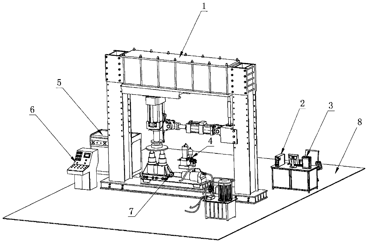
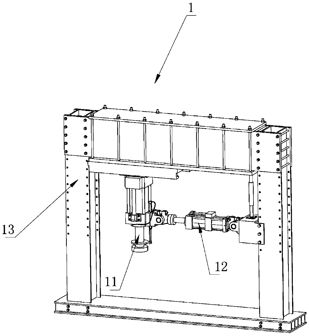
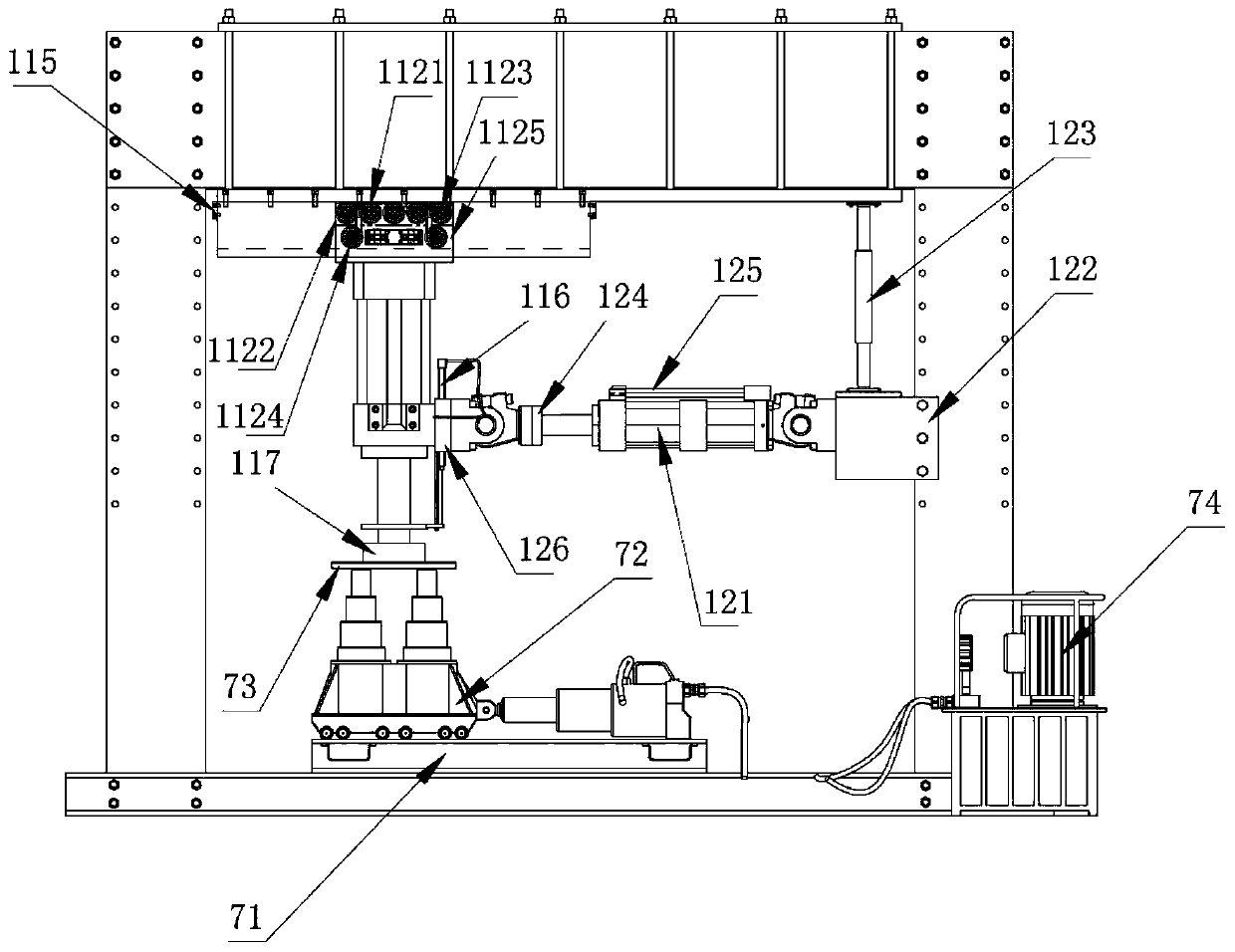
[0037] According to the test requirements of the hydraulic rerailer, the present invention designs a hydraulic rerailer test system suitable for different models, which is closer to the real working ...


PUM


Abstract

The invention discloses a hydraulic rerailer test system and test method. The hydraulic rerailer test system comprises a test device, an upper computer, a controller, an oil distributor, a hydraulic oil source, a hydraulic substation control console, a control system, a hydraulic pipeline, a tested hydraulic rerailer and a foundation. The test method comprises a rated load test step, a static loadtest step, a pressure maintaining test step, an emergency test step and a safety test step. The self-weight of an on-site rescue vehicle is simulated by adopting a vertical load applied by a verticalservo actuator, a transverse load applied by a transverse servo actuator is adopted to simulate the transverse moving resistance borne by a locomotive vehicle in the driving accident rescue process,and the load can be adjusted in time according to the transverse resistance of hydraulic rerailers of different models. The defects that the test model is single and the whole rescue process cannot besimulated are overcome, and the test efficiency, the detection flexibility and the detection accuracy are improved; and the hydraulic substation control console is arranged, so that an operator can remotely operate and control the start and stop of an oil quantity and an oil source, and the test safety is improved.

Description

technical field [0001] The invention relates to the technical field of testing and testing of driving accident rescue equipment in rail transit, in particular to a hydraulic rerailer testing system and testing method. Background technique [0002] Hydraulic rerailer is one of the necessary equipment for railway accident rescue, and plays a very important role in accident rescue; especially for large-scale road maintenance machinery, it is stipulated that each car must be equipped with hydraulic rerailer. The hydraulic rerailer has become the main rescue tool for driving accident rescue in rail transit, and its reliability and quality stability affect whether the driving accident rescue work can be carried out smoothly. Quality inspection is very important to ensure the safety of railway transportation. At present, the quality of hydraulic rerailers is uneven. During the road rescue process, there have been many secondary accidents in which rescue equipment failed and rescue ...

Claims


Application Information

Patent Timeline
Patent Type & Authority Applications(China)
IPC IPC(8): G01M13/00
CPCG01M13/00
Inventor 于兆华杨贺曹玉董博宋瑞卢翀李子华
Owner 中铁检验认证中心有限公司
Why Eureka
Try Eureka