A rotary exhaust gas dust removal device for factories

A dust-removing device and rotary technology, applied in cleaning methods and utensils, using liquid separating agents, separating methods, etc., can solve the problems of inconvenient disassembly and replacement, waste of production time, low cleaning efficiency, etc., and achieve ingenious design of linkage structure structure. Reasonable, lower manufacturing cost, high cleaning efficiency

Active Publication Date: 2021-11-26
广西永福华源科技有限公司
View PDF17 Cites 0 Cited by
  • Summary
  • Abstract
  • Description
  • Claims
  • Application Information

AI Technical Summary

Problems solved by technology

[0006] The purpose of the present invention is to provide a rotary waste gas dedusting device for factories to solve the problem that most of the inner walls of the tanks proposed in the above background technology need to be manually cleaned by operating the cleaning parts, which takes up manpower and needs to be shut down when cleaning, and the cleaning efficiency is low. Low, occupying and wasting normal production time, affecting output and economic benefits. In addition, the optimization design of the installation and positioning structure of cleaning parts is not reasonable enough, resulting in inconvenient disassembly and replacement.

Method used


Image

  • A rotary exhaust gas dust removal device for factories
  • A rotary exhaust gas dust removal device for factories
  • A rotary exhaust gas dust removal device for factories

Examples


Embodiment Construction

[0032] The following will clearly and completely describe the technical solutions in the embodiments of the present invention with reference to the accompanying drawings in the embodiments of the present invention. Obviously, the described embodiments are only some, not all, embodiments of the present invention.

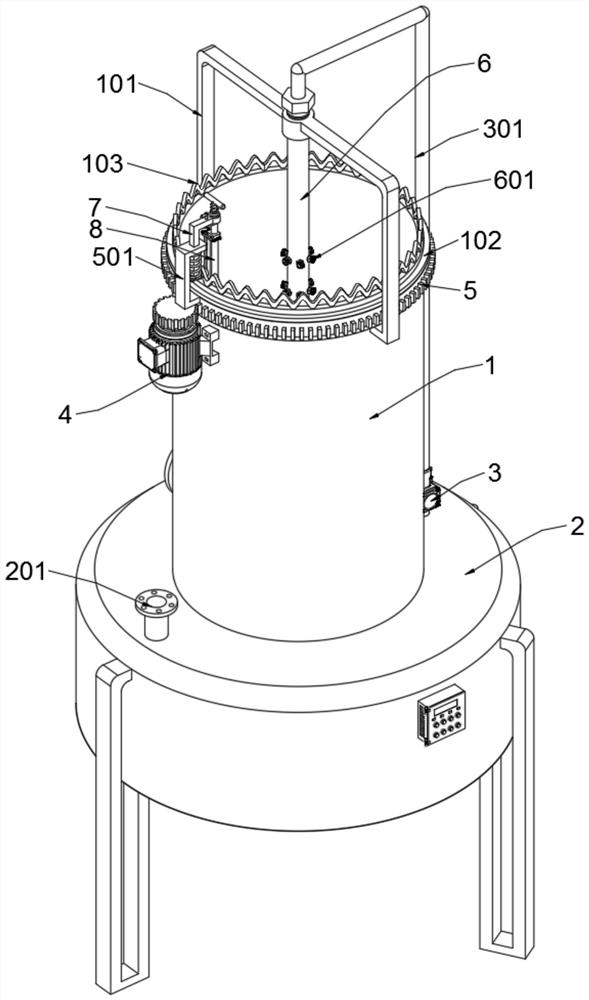
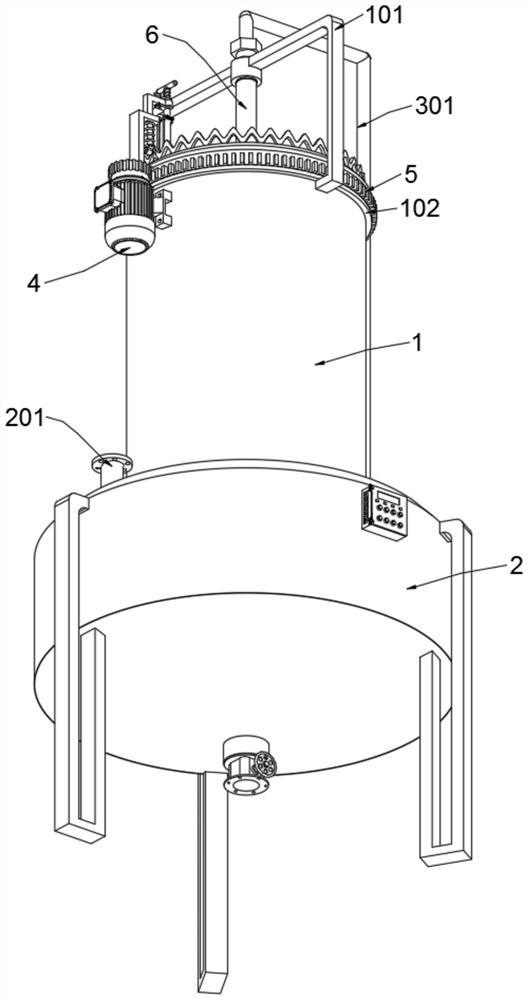
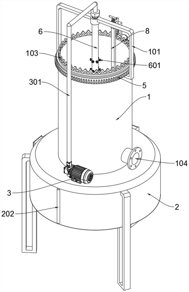
[0033] see Figure 1 to Figure 11, an embodiment provided by the present invention: a factory rotary exhaust gas dedusting device, including a settling tank 2, a circulating water pump 3, an L-shaped ejector rod 7 and a vertical support square rod 8, and the settling tank 2 includes a water supply pipe 201 And the water level glass tube 202, the bottom of the settling tank 2 is welded with a mud gathering hopper, the bottom of the gathering hopper is equipped with a discharge valve, and the annular top plate of the settling tank 2 is welded and communicated with a water supply pipe 201; The center of the top of the settling tank 2 is supported and welded with a dust ...


PUM


Abstract

The invention discloses a rotary waste gas dedusting device for factories, which relates to the technical field of dedusting equipment and solves the problem that in the existing dedusting device, most of the inner walls of the tank need to be cleaned manually by operating the cleaning parts, which takes up manpower and needs to be shut down when cleaning. , The cleaning efficiency is low, occupying and wasting normal production time, affecting output and economic benefits. A rotary waste gas dedusting device for a factory, including a settling tank, a circulating water pump, an L-shaped ejector rod and a vertical support square bar. The settling tank includes a water supply pipe and a water level glass pipe. The bottom of the settling tank is welded with a mud Accumulation hopper, a discharge valve is installed at the bottom of the accumulation hopper, and a water supply pipe is welded and connected to the annular top plate of the settling tank. The L-shaped insertion rod in the present invention can insert and fix the positioning plate and the top cross-bracing plate section of the L-shaped ejector rod together, so that the vertical support square rod can be kept fixed to prevent the installation of thin plates and nylon brushes from rotating and deflecting when they are rotating and wiping. .

Description

technical field [0001] The invention relates to the technical field of dust removal equipment, in particular to a rotary waste gas dust removal device for factories. Background technique [0002] Air pollution is one of the most prominent environmental problems in our country at present. Exhaust gas refers to the poisonous and harmful gas with dust discharged by human beings in the process of production and life. [0003] A large amount of flue gas is produced in industrial production activities, and the dust contained in the flue gas is a substance that pollutes the atmosphere. Therefore, the problem of industrial flue gas pollution has always troubled people. With the development of the economy, the requirements for environmental protection are getting higher and higher, and the problem of industrial flue gas pollution has become increasingly prominent. For a long time, people have also proposed and designed exhaust gas dust removal devices to solve this problem, among whi...

Claims


Application Information

Patent Timeline
Patent Type & Authority Patents(China)
IPC IPC(8): B01D47/06B08B9/087
CPCB01D47/06
Inventor 洪献彬
Owner 广西永福华源科技有限公司
Why Eureka
Try Eureka