New energy stirring device and using method

A technology of stirring device and new energy, which is applied to mixers with rotary stirring devices, accessories of mixers, chemical instruments and methods, etc., can solve the problems of low stirring efficiency, poor stirring effect, poor stirring effect, etc. The effect of efficiency

Inactive Publication Date: 2020-07-28
绍兴市亚索新能源科技有限公司
View PDF2 Cites 16 Cited by
  • Summary
  • Abstract
  • Description
  • Claims
  • Application Information

AI Technical Summary

Problems solved by technology

[0003] When the existing stirring device for new energy is actually used, it only performs simple stirring by rotating the stirring rod, and the stirring efficiency is low and the stirring effect is not good.
[0004] The Chinese patent with the patent number CN201911197577.5 in the prior art discloses a new energy stirring device. By making the first transmission shaft and the second transmission shaft rotate in opposite directions, the stirring rods on the top and bottom of the housing are rotated in opposite directions. direction, but the top and bottom of the shell do not move relative to each other, and the stirring effect is still poor; the Chinese patent No. CN201910190717.X in the prior art discloses a stirring device, which makes the active stirring shaft and driven stirring shaft The rotation direction of the shaft is opposite to improve the stirring efficiency, and there is no stirring dead angle, but it cannot stir the substances that adhere to the inner wall of the tank or sink to the bottom wall of the tank

Method used


Image

  • New energy stirring device and using method
  • New energy stirring device and using method
  • New energy stirring device and using method

Examples


Embodiment 1

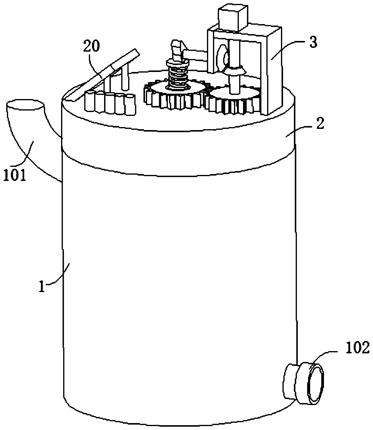
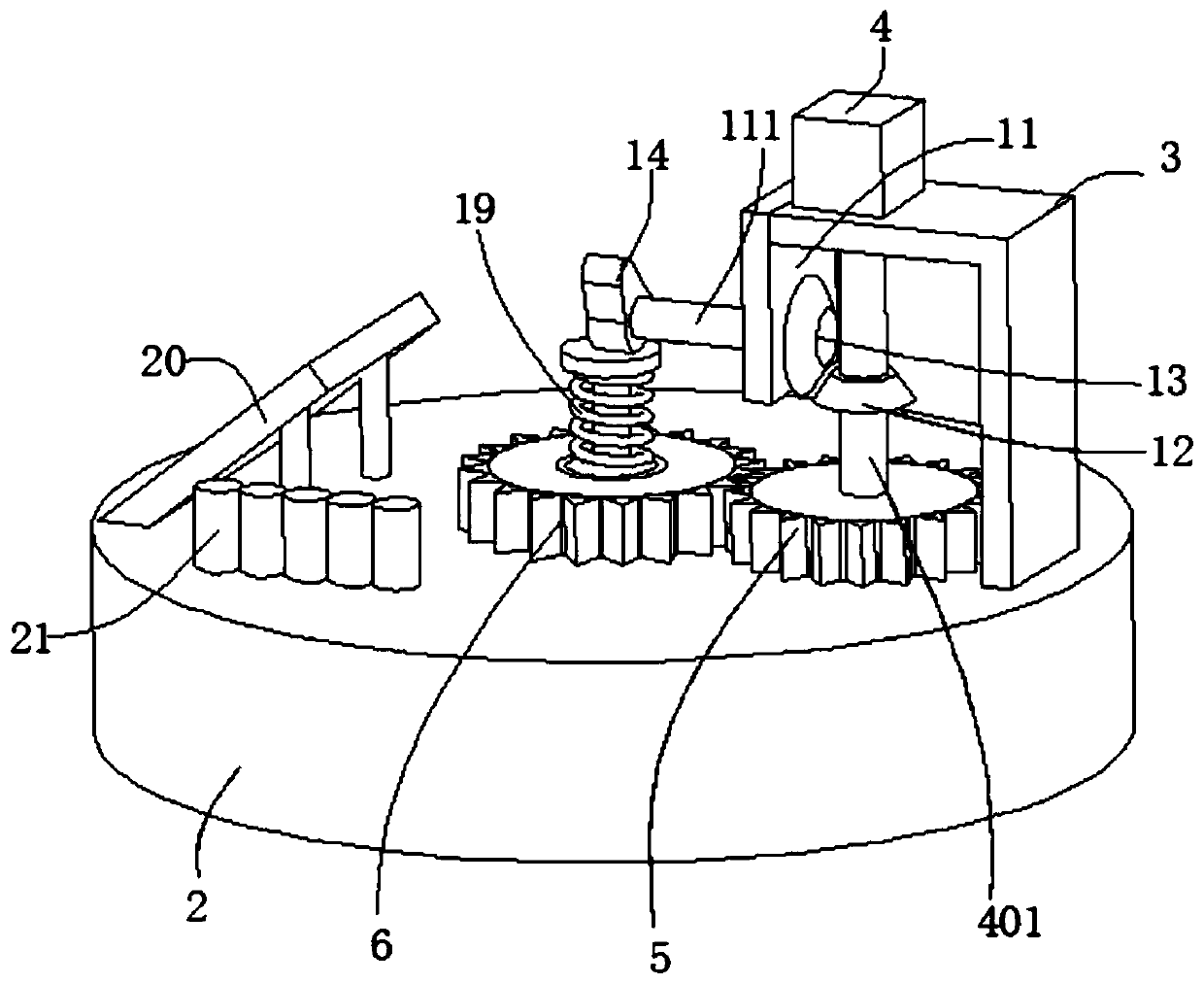
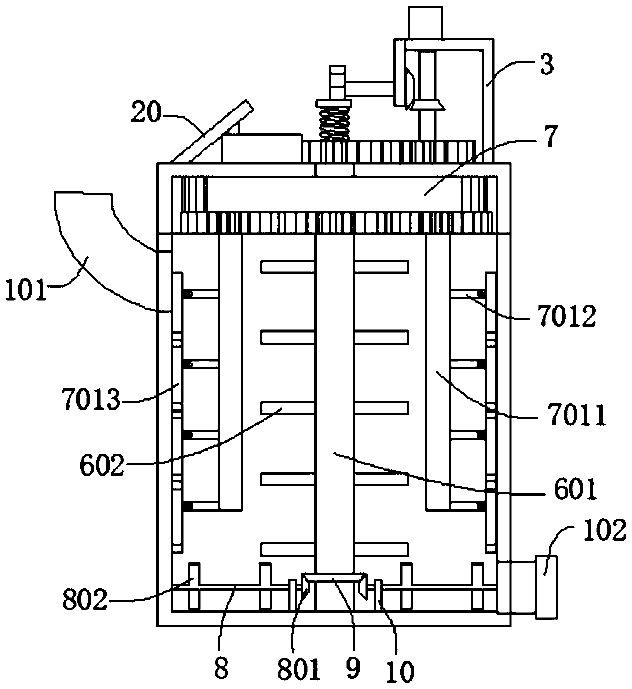
[0037] refer to figure 1 , image 3 , Figure 4 , Figure 5 and Figure 7, a new energy stirring device, including a box body 1 and a box cover 2, the box cover 2 is connected to the top of the box body 1, the outer wall of the box cover 2 is connected to a support seat 3, the top of the support seat 3 is connected to a motor 4, and the motor 4 The output end of the rotating shaft 401 is connected with the rotating shaft 401, and the end of the rotating shaft 401 far away from the motor 4 passes through the support base 3 and is connected with the first gear 5, the outer wall of the first gear 5 is engaged with the second gear 6, and the inner wall of the second gear 6 is connected with the drive shaft 601, the outer wall of the drive shaft 601 is connected with a third gear 6011, the third gear 6011 is rotatably connected to the bottom wall of the case cover 2, the bottom wall of the case cover 2 is also rotatably connected with the rotating disk 7, and the inner wall of t...

Embodiment 2

[0040] refer to figure 1 , image 3 , Figure 4 and Figure 6 , a new energy stirring device, which is basically the same as that of Embodiment 1, furthermore, the inner walls on both sides of the box body 1 are rotatably connected with a rotating rod 8, the outer wall of the rotating rod 8 is connected with a first bevel gear 801, and the outer wall of the driving shaft 601 The second bevel gear 9 meshing with the first bevel gear 801 is connected, the third stirring rod 802 is connected to the outer wall of the rotating rod 8, the fixed plate 10 is connected to the bottom wall of the box body 1, and the rotating rod 8 is connected to the fixed plate 10 in rotation , the outer wall of the support seat 3 is connected with a connecting plate 11, the connecting plate 11 is connected with a rotating shaft 111 for rotation, the outer wall of the rotating shaft 401 is connected with a third bevel gear 12, and the outer wall of the third bevel gear 12 is engaged with a fourth beve...

Embodiment 3

[0043] refer to figure 1 and figure 2 , a new energy stirring device, which is basically the same as Embodiment 1, furthermore, the outer wall of the case cover 2 is connected with a solar panel 20, and the outer wall of the case cover 2 is also connected with a storage battery assembly 21, and the solar panel 20 and the storage battery assembly 21 are connected with each other. The motor 4 is electrically connected; by installing a solar panel 20 on the top of the case cover 2, the solar energy can be converted into electrical energy and stored inside the storage battery assembly 21, and the storage battery assembly 21 is electrically connected with the motor 4 to provide electrical energy for the motor 4. This way of power supply is more energy-saving and environmentally friendly.

[0044] The invention also discloses a method for using a new energy stirring device, which includes the following steps:

[0045] S1: By installing a solar panel 20 on the top of the case cove...


PUM


Abstract

The invention discloses a new energy stirring device and a using method, and belongs to the technical field of new energy. The new energy stirring device comprises a box body and a box cover, the boxcover is connected to the top of the box body; the outer wall of the box cover is connected with a support seat; the top of the support seat is connected with a motor; the output end of the motor is connected with a rotation shaft; the end, away from the motor, of the rotation shaft penetrates the support seat and is connected with a first gear, the outer wall of the first gear is in engaged witha second gear, the inner wall of the second gear is connected with a driving shaft, and the outer wall of the driving shaft is connected with a third gear, which is rotationally connected to the bottom wall of the box cover. The bottom wall of the box cover is also rotationally connected to a rotating disc. The inner wall of the box cover is connected to an annular rack. The interior of the box body is stirred through three stirring rods, the stirring efficiency and the stirring effect are improved, stirring dead corners are avoided, in the stirring process, materials adhered to the inner wallof the box body are scraped, the box body is convenient to clean, and the uniformity in the stirring process is further improved.

Description

technical field [0001] The invention relates to the field of new energy technology, in particular to a new energy stirring device and a method for using it. Background technique [0002] New energy, also known as unconventional energy, refers to various energy forms other than traditional energy. Renewable energy, including solar energy, biomass energy, wind energy, geothermal energy, wave energy, ocean current energy and tidal energy, as well as the thermal cycle between the ocean surface and the deep layer, etc., in addition, there are hydrogen energy, biogas, alcohol, methanol, etc., Energy sources such as coal, oil, natural gas, and water energy that have been widely used are called conventional energy. In daily life, by using new energy for power supply, resources can be saved and sustainable energy development can be achieved. [0003] When the existing stirring device related to new energy is used in practice, it only performs simple stirring through the rotation of ...

Claims


Application Information

Patent Timeline
Patent Type & Authority Applications(China)
IPC IPC(8): B01F7/20B01F7/00B01F7/04B01F13/02B01F15/00B01F27/906B01F33/40
CPCB01F27/17B01F27/2122B01F27/213B01F27/232B01F27/191B01F27/706B01F27/906B01F27/85B01F33/4021B01F35/123B01F35/32055
Inventor 张小庆
Owner 绍兴市亚索新能源科技有限公司
Why Eureka
Try Eureka