Automatic automobile plate spring forming heat treatment line and work method thereof

An automatic forming and auto sheet technology, which is applied in heat treatment furnaces, heat treatment equipment, manufacturing tools, etc., can solve the problems of time-consuming manual loading and unloading, laborious work rhythm, and inability to close reed edges, so as to save work space and facilitate the output of workpieces Material, the effect of smooth feeding

Pending Publication Date: 2020-07-28
山东森德数控机械有限公司
View PDF0 Cites 4 Cited by
  • Summary
  • Abstract
  • Description
  • Claims
  • Application Information

AI Technical Summary

Problems solved by technology

[0002] At present, the leaf spring quenching production line adopts manual loading and unloading from the straightening machine to the quenching forming machine, and manual loading and unloading from the quenching oil tank machine to the tempering furnace. Manual loading and unloading is time-consuming and laborious. The efficiency is low; and the leaf spring straightening machine in the existing leaf spring quenching production line can only straighten the reed, and cannot work on the edge of the reed; the replacement of the leaf spring quenching machine in the existing leaf spring quenching production line is different The position of all clamping teeth must be manually adjusted once when specifying the size of the leaf spring reed. Manual adjustment is time-consuming and laborious; moreover, the feeding mechanism of the leaf spring automatic quenching device in the leaf spring quenching production line has no leaf spring restraint oil-feeding mechanism, and the plate The spring is easy to flip and slip when the supporting mechanism is oiled, causing failure

Method used


Image

  • Automatic automobile plate spring forming heat treatment line and work method thereof
  • Automatic automobile plate spring forming heat treatment line and work method thereof
  • Automatic automobile plate spring forming heat treatment line and work method thereof

Examples


Embodiment Construction

[0032] The present invention is described in further detail now in conjunction with accompanying drawing.

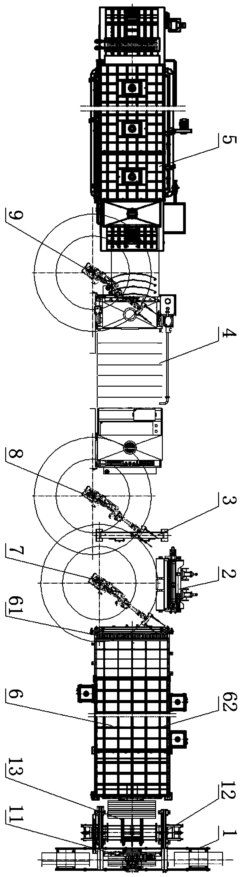
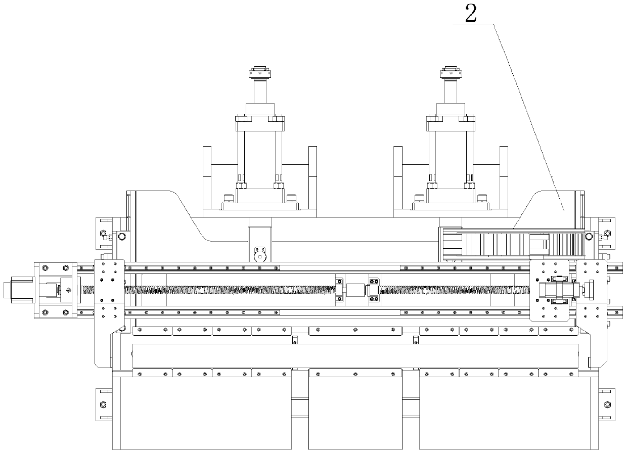
[0033] Such as Figure 1-7 , an automobile leaf spring automatic forming heat treatment line, comprising an automatic feeding device 1, a leaf spring quenching furnace 6, a leaf spring straightening machine 2, a leaf spring forming machine 3, a quenching device 4 and a tempering furnace 5, the production line The layout is arranged side by side in a "one" shape. This layout makes reasonable use of space and saves work space.

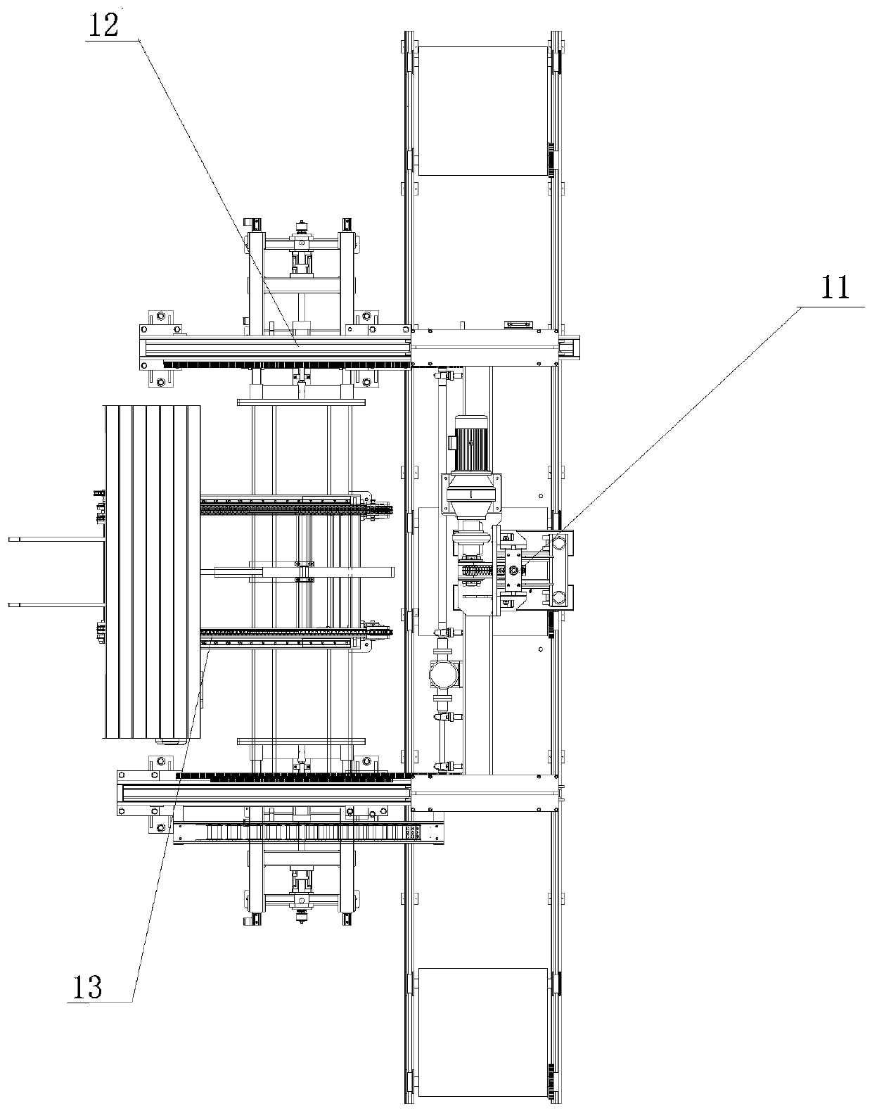
[0034] The automatic feeding device 1 is equipped with an electromagnetic sucker 11, and adopts the automatic centering feeding method. First, the electric hoist is used to drive the electromagnetic sucker 11 to complete the loading and unloading of the entire row of reeds, and then the centering mechanism 12 in front of the furnace aligns the ends of the reeds. Finally, the small step feeding mechanism 13 rotates the reeds one by one to the quenc...


PUM


Abstract

The invention relates to an automatic automobile plate spring forming heat treatment line and a work method thereof. An automatic feeding device, a plate spring quenching heating furnace, a plate spring straightening machine, a plate spring forming machine, a quenching device and a tempering heating furnace are included. The automatic feeding device conveys reeds to a feeding port of the quenchingheating furnace after centring the reeds, and the reeds are conveyed to a quenching heating furnace discharging port to be heated from the quenching heating furnace via a stepping mechanism. A firstcarrying robot conveys the reeds at the quenching heating furnace discharging port to the plate spring straightening machine, and the straightened reeds are conveyed to the plate spring forming machine. A second carrying robot conveys the formed reeds to a workpiece oil inlet mechanism of the quenching device, the workpiece oil inlet mechanism places the reeds on a stepping conveying mechanism, the quenching device brings the reeds into oil for quenching, and a workpiece oil discharging mechanism is used for supporting out the quenched reeds from the stepping conveying mechanism. A third carrying robot places the quenched reeds on the tempering heating furnace from the workpiece oil discharging mechanism, and automatic reed forming heat treatment is finished.

Description

technical field [0001] The invention belongs to the technical field of production and manufacture of automobile leaf springs, and in particular relates to an automatic forming heat treatment line for automobile leaf springs and a working method thereof. Background technique [0002] At present, the plate spring quenching production line adopts manual loading and unloading from the straightening machine to the quenching forming machine, and manual loading and unloading from the quenching oil tank machine to the tempering furnace. Manual loading and unloading is time-consuming and laborious. The efficiency is low; and the leaf spring straightening machine in the existing leaf spring quenching production line can only straighten the reed, and cannot work on the edge of the reed; the replacement of the leaf spring quenching machine in the existing leaf spring quenching production line is different The position of all clamping teeth must be manually adjusted once for the leaf spr...

Claims


Application Information

Patent Timeline
Patent Type & Authority Applications(China)
IPC IPC(8): C21D9/02C21D1/63
CPCC21D1/63C21D9/0062C21D9/02
Inventor 石学友步砚杰王祥洲郭兆友王杰陈允明胥幼林杜昆赵荣猛王颖白利刚
Owner 山东森德数控机械有限公司
Why Eureka
Try Eureka