
High-pressure jet grouting pile construction method

A technology of high-pressure rotary jetting pile and construction method, which is applied in sheet pile wall, foundation structure engineering, construction and other directions, can solve the problems of unsuitable soil quality, easy environmental pollution, and high construction cost, so as to expand the scope of application and expand the scope of reinforcement. , the effect of increasing the amount of grouting

Inactive Publication Date: 2020-07-28
珠海十字门中央商务区建设控股有限公司
View PDF3 Cites 2 Cited by
  • Summary
  • Abstract
  • Description
  • Claims
  • Application Information

AI Technical Summary

Problems solved by technology

[0004] The construction method adopted by the high-pressure rotary grouting pile in the prior art is easy to pollute the environment, and the construction cost is high. It is not suitable for special soil quality that cannot make the sprayed slurry solidify; The pebbles, boulders, and boulders in the stratum with a skeleton structure, the groundwater flow rate is too large and the foundation engineering that has already flooded, because the groundwater is erosive, the application also has limitations.

Method used


Image

  • High-pressure jet grouting pile construction method
  • High-pressure jet grouting pile construction method
  • High-pressure jet grouting pile construction method

Examples


Embodiment Construction

[0034] The technical solutions of the present invention will be clearly and completely described below in conjunction with the accompanying drawings. Apparently, the described embodiments are some of the embodiments of the present invention, but not all of them. Based on the embodiments of the present invention, all other embodiments obtained by persons of ordinary skill in the art without making creative efforts belong to the protection scope of the present invention.

[0035] In the description of the present invention, it should be noted that the terms "center", "upper", "lower", "left", "right", "vertical", "horizontal", "inner", "outer" etc. The indicated orientation or positional relationship is based on the orientation or positional relationship shown in the drawings, and is only for the convenience of describing the present invention and simplifying the description, rather than indicating or implying that the referred device or element must have a specific orientation, ...


PUM

PropertyMeasurementUnit
diameteraaaaaaaaaa

Abstract

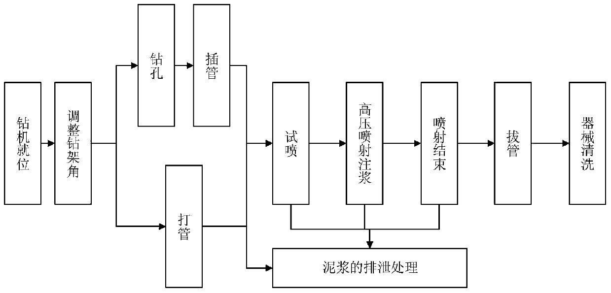
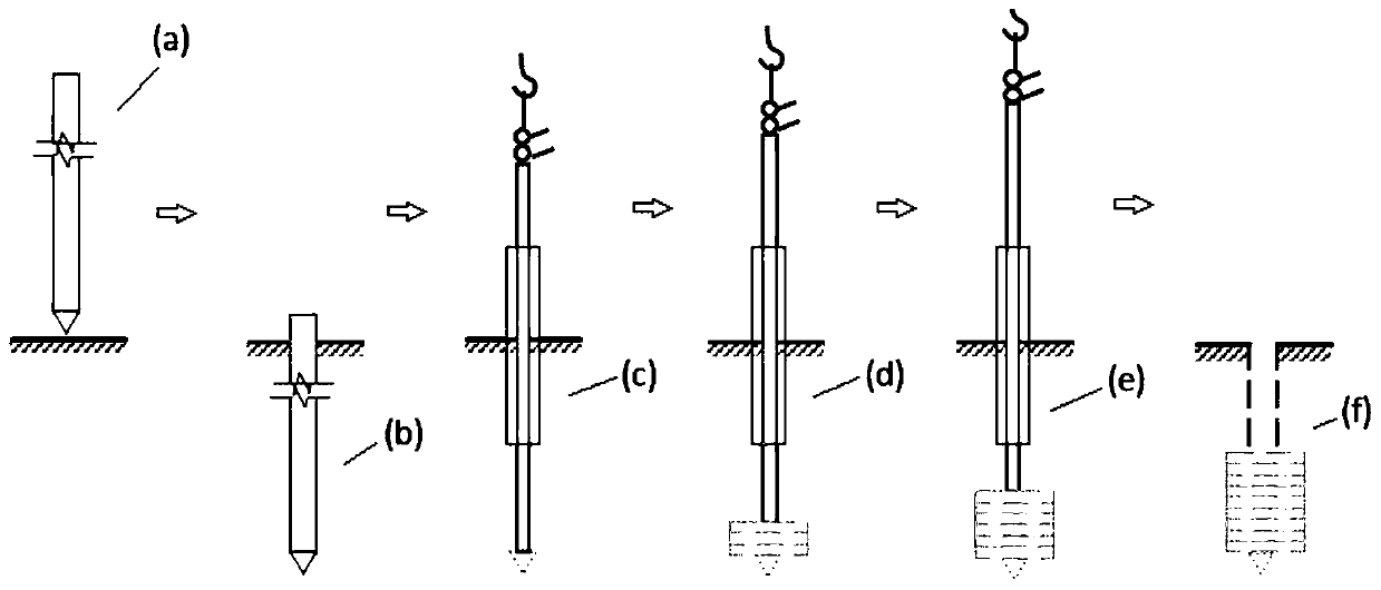
The invention provides a high-pressure jet grouting pile construction method which achieves the technical effects of reducing construction cost and further adapting to the construction environment ofa silt geological layer by improving an existing high-pressure jet grouting pile construction technology. The method comprises the following steps that a drilling machine is installed, specifically, the drilling machine is arranged on a set hole position, inclination of a jet grouting pipe is less than or equal to 1.5%, and the distance between an injection hole and a high-pressure grouting pump is less than or equal to 50 m; drilling is carried out, specifically, the deviation between a drilling position and design is less than or equal to 50 mm, the drill bit inclination is smaller than or equal to 1.5%, and a core barrel is pulled out after drilling; pipe inserting is carried out, specifically, the jet grouting pipe is inserted into the stratum by a preset depth; spraying and grouting are carried out, specifically, spraying and grouting are carried out from bottom to top, and after rotating and spraying are carried out by 1 min at the bottom of a pile, rotation, lifting and sprayingare simultaneously carried out; the grouting pipe is lifted up, specifically, when the grouting pipe is lifted, a drilling rod is synchronously and continuously rotated without interruption, and theslurry discharge amount is between 10% and 20%; the overlapping length of subsection lifting of the grouting pipe is greater than or equal to 100 mm; washing is carried out, specifically, the groutingpipe and an operation machine are washed until no residual cement slurry exists; and equipment is moved, specifically, relevant equipment such as the drilling machine is moved to a new hole positionto carry out next pile construction.

Description

technical field [0001] The invention relates to the technical field of construction methods for underground diaphragm walls, in particular to a construction method for high-pressure rotary grouting piles. Background technique [0002] The high-pressure rotary grouting pile is to spray the cement slurry into the soil layer and mix with the soil with the high-pressure rotating nozzle to form a continuous lapped cement reinforcement; the grouting form of the high-pressure jet grouting method is divided into rotary jet grouting and pendulum jet grouting There are three types of grouting and fixed jet grouting, of which high-pressure jet grouting and fixed jetting are suitable for loose formations with a particle size of no more than 20mm, pendulum jetting is suitable for loose formations with a particle size of no more than 60mm, and large-angle pendulum jetting is suitable for loose formations with a particle size of no more than 20mm. For loose formations larger than 100mm, ro...

Claims


Application Information

Patent Timeline
Patent Type & Authority Applications(China)
IPC IPC(8): E02D5/46E02D15/04C04B28/04
CPCC04B28/04C04B2111/00155E02D5/46E02D15/04C04B22/06C04B2103/10
Inventor 米向东周吉林范银忠钟畅迁刘峰韩春鹏
Owner 珠海十字门中央商务区建设控股有限公司
Learn More