
Water-saving pedestal pan

A toilet and sinking technology, which is applied in the field of bathroom, can solve the problems of poor brushing and spraying effect, loss of conduction kinetic energy of flushing water, and inability to distribute water to the toilet, and achieves good water saving effect, enhanced washing effect, and structural compact effect

Pending Publication Date: 2020-07-28
谷力(厦门)科技有限公司
View PDF0 Cites 3 Cited by
  • Summary
  • Abstract
  • Description
  • Claims
  • Application Information

AI Technical Summary

Problems solved by technology

The brush ring water delivery pipe and the jet water delivery pipe inside the existing toilet are common, so the water volume cannot be reasonably distributed to the brush ring water delivery pipe and the jet water delivery pipe of the toilet when the drain valve is opened
The "water volume ratio" assigned to the brush ring water delivery pipe and the spray water delivery pipe varies with the working water level of the toilet tank, which may easily cause the amount of "brush ring water" or "siphon water" in the toilet to exceed the toilet flushing demand and waste water
At the same time, due to the limited water storage capacity of the water tank of the toilet, when the drainage is turned on, the 1-2 liters of water with the highest pressure are directly used to fill in the common auxiliary water pipeline at the front end of the brush ring water pipeline and the spray water pipeline, resulting in a waste of flushing water. Loss of transmitted kinetic energy, less effective brushing and jetting

Method used


Image

  • Water-saving pedestal pan
  • Water-saving pedestal pan
  • Water-saving pedestal pan

Examples


Embodiment 1

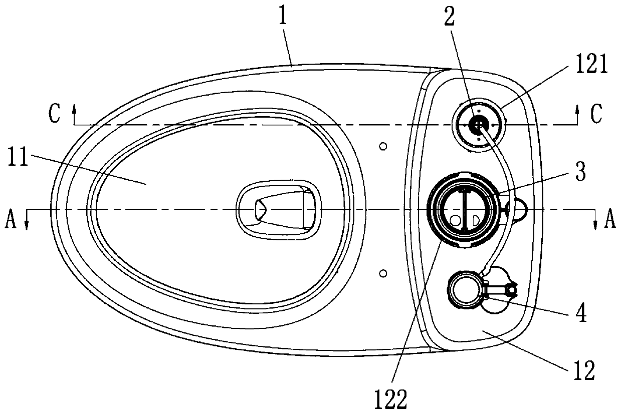
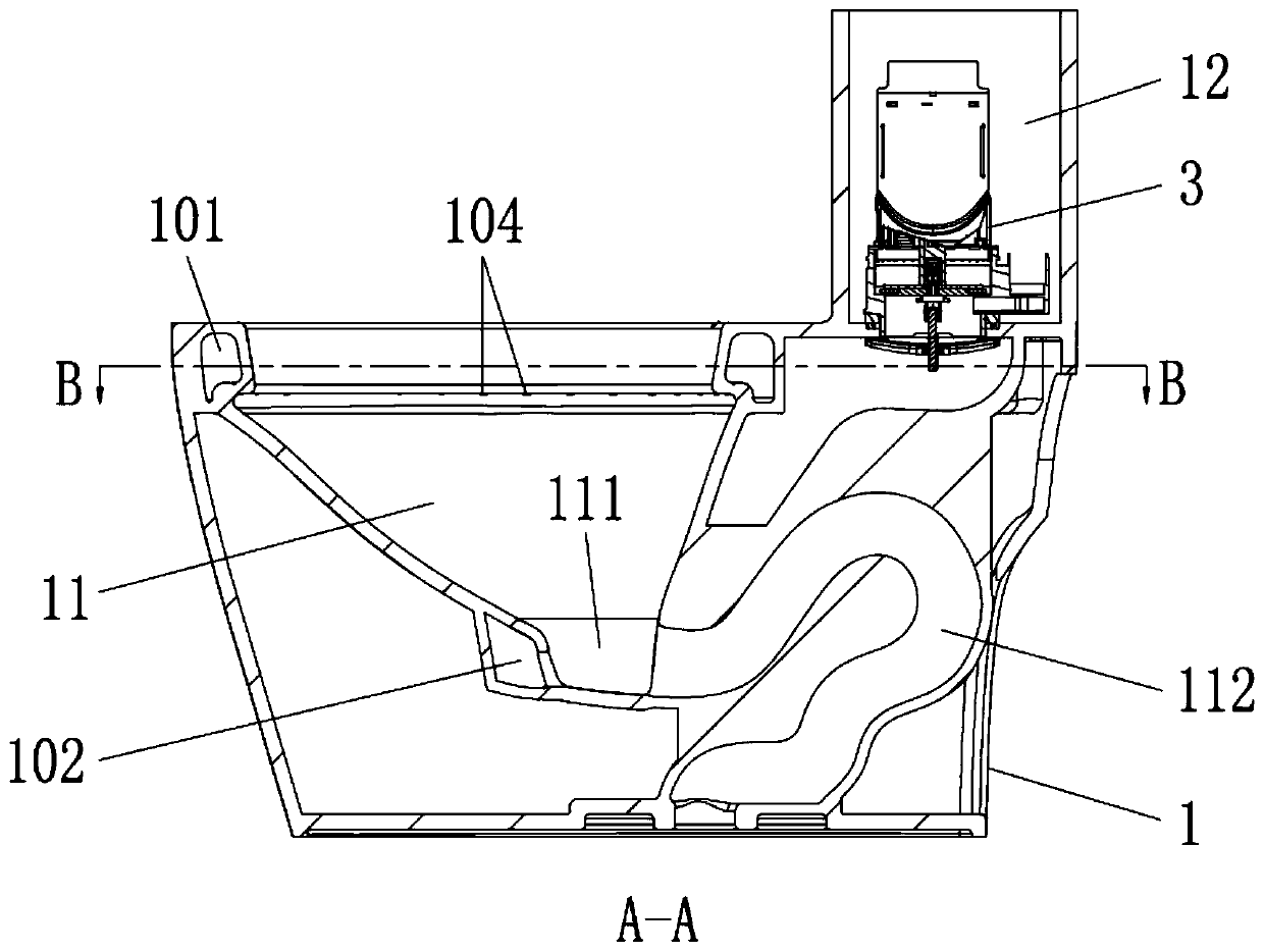
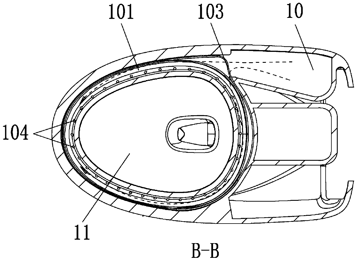
[0060] Such as Figure 1-4 As shown, a water-saving toilet includes a toilet body 1, a toilet 11 and a water storage tank 12 are arranged on the toilet body 1, a sinking bay 111 is provided at the bottom of the sinking 11, and the sinking bay 111 is connected with Sewage siphon 112. The inside of the toilet body 1 is provided with a scrubbing water delivery pipeline 101 for flushing the surrounding wall of the urinal 11 and a spray water delivery pipeline 102 for flushing the bottom of the cesspool 11, and the scrubbing water delivery pipeline 101 and the jet water delivery pipeline The pipes 102 are arranged independently of each other. The bottom of the water storage tank 12 is provided with a first installation hole 121 and a second installation hole 122 respectively, the first drainage valve 2 is installed in the first installation hole 121, the second drainage valve 3 is installed in the second installation hole 122, and the second drainage valve 3 is installed in the se...

Embodiment 2

[0078] Such as Figure 23-27 As shown, the difference between the present embodiment and the first embodiment is only that the brushing water delivery pipeline 101 is an annular water diversion tank with side openings, and the two sides of the transition water chamber 10 are respectively provided with a first channel connected with the annular water diversion tank. The direction of the swirl injection port 105 and the second swirl injection port 106, the first swirl injection port 105 and the second swirl injection port 106 are all the same as the flow direction of the flushing water of the annular water diversion tank. The rest of the structure of this embodiment is the same as that of Embodiment 1.

[0079] After the second drain valve 3 is opened, the water in the water storage tank 12 flows into the jetting water delivery pipeline 102 through the second installation port 122 to flush the bottom of the urinal 11 . When the water level drops to a certain height, the first d...

Embodiment 3

[0081] Such as Figure 28-30 As shown, the difference between this embodiment and the first embodiment is only that the first drain valve 2 and the second drain valve 3 are flap-type drain valves. The top of the first drain valve 2 is provided with a first chain 209 for driving it to open, and the top of the second drain valve 3 is provided with a second chain 300 for driving it to open. The tops of the first hanging chain 209 and the second hanging chain 300 are respectively connected with the connecting rod 61, and the side of the toilet body 1 is provided with the connecting rod 61 and is used to drive the connecting rod 61 to rotate to open the first drain valve 2 and the second connecting rod. The wrench 62 of the second drain valve 3. An overflow pipe 29 communicating with the transition water chamber 10 is installed on the top of the first drain valve 2 . The rest of the structure of this embodiment is the same as that of Embodiment 1.

[0082] In this implementation...


PUM


Abstract

The invention discloses a water-saving pedestal pan, which comprises a pedestal pan body. A urinal and a water storage tank are arranged on the pedestal pan body, a water sinking bay is arranged at the bottom of the urinal, and the water sinking bay is connected to a blowdown siphon. A brushing water conveying pipeline used for flushing the peripheral wall of the urinal and a spraying water conveying pipeline used for flushing the bottom of the urinal are arranged in the pedestal pan body. A first mounting hole and a second mounting hole are formed in the bottom of the water storage tank respectively, a first drain valve is mounted in the first mounting hole, and a second drain valve is mounted in the second mounting hole. The brushing water conveying pipeline is communicated with the first mounting hole, and the spraying water conveying pipeline is communicated with the second mounting hole. By controlling the displacement of the first drain valve and the second drain valve, water canbe reasonably distributed into the brushing water conveying pipeline and the spraying water conveying pipeline of the pedestal pan, water waste is avoided, a good water saving effect is achieved, meanwhile, efficient transfer of water flow can be achieved, kinetic energy losses in the conduction process are small, and the flushing effect is good.

Description

technical field [0001] The invention relates to the bathroom field, in particular to a water-saving toilet. Background technique [0002] The inside of the toilet is usually provided with two water delivery pipes, one of which is a brush ring water delivery pipeline for flushing the surrounding wall of the urinal, and the other is a jet water delivery pipeline for flushing the bottom of the urinal. The brush ring water delivery pipeline and the spray water delivery pipeline inside the existing toilet are common, so the water volume cannot be reasonably distributed to the brush ring water delivery pipeline and the spray water delivery pipeline of the toilet when the drain valve is opened. The "water volume ratio" assigned to the brush ring water delivery pipe and the spray water delivery pipe varies with the working water level of the toilet tank, which may easily cause the amount of "brush ring water" or "siphon water" in the toilet to exceed the toilet flushing demand and w...

Claims


Application Information

Patent Timeline
IPC IPC(8): E03D11/06E03D11/13E03D11/18E03D1/00E03D1/34
CPCE03D1/00E03D1/34E03D11/06E03D11/13E03D11/18Y02A20/40
Inventor 陈雪瑜
Owner 谷力(厦门)科技有限公司
Learn More