Downhole tubing and sucker rod heating device

A technology for heating devices and sucker rods, applied in the direction of isolation devices, drill pipes, drill pipes, etc., can solve the problem of high power consumption, achieve the effects of reduced power consumption, shortened contact time, and reduced possibility

Active Publication Date: 2021-06-22
大庆市鹤翔机械有限公司
View PDF13 Cites 1 Cited by
  • Summary
  • Abstract
  • Description
  • Claims
  • Application Information

AI Technical Summary

Problems solved by technology

[0003] The purpose of the present invention is to solve the problem of high power consumption of existing downhole tubing and sucker rod heating methods, and to provide a new type of downhole tubing and sucker rod heating device

Method used


Image

  • Downhole tubing and sucker rod heating device
  • Downhole tubing and sucker rod heating device
  • Downhole tubing and sucker rod heating device

Examples


specific Embodiment approach 1

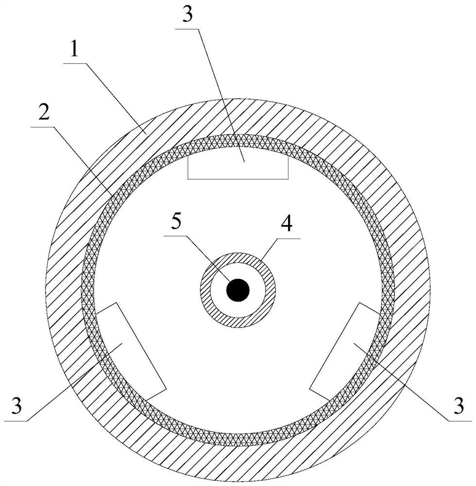
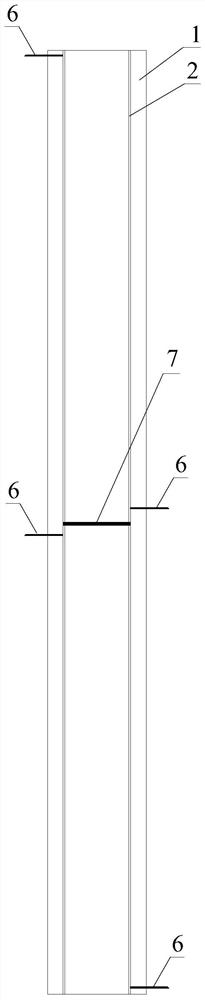
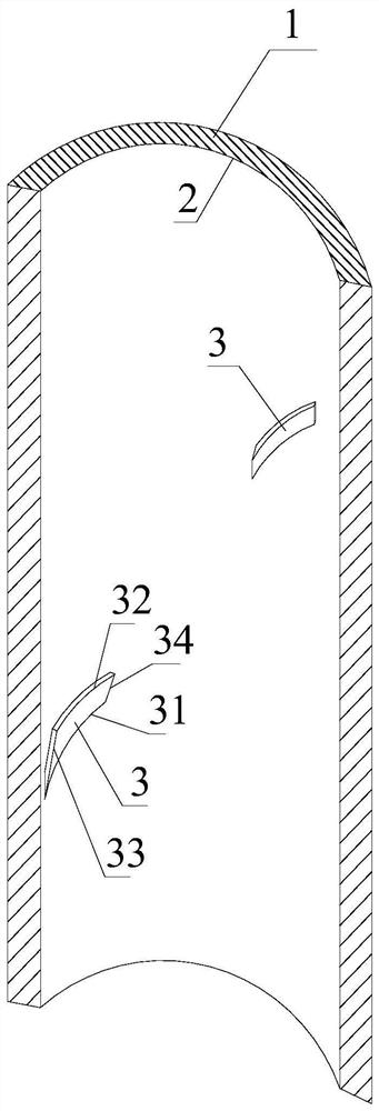
[0035] The downhole oil pipe and sucker rod heating device provided in this embodiment uses an intermediate frequency heating power supply and an intermediate frequency transformer to provide intermediate frequency current to the sucker rod 4 and the internal cable 5. In order to increase the heating temperature, the cable in the hollow sucker rod can use Skin heating cables. On this basis, improvements are made to the inner wall of the oil pipe. like figure 1 As shown, the oil pipe 1 in this embodiment is made of insulating material, and a metal layer is arranged on the inner wall of the oil pipe 1, which is called the first metal layer 2. The first metal layer 2 can be a thin metal plate, or it can be attached to the oil pipe. 1 For the metal film on the inner wall, there is no restriction on which metal to use, and it can be selected according to the actual situation. In principle, try to choose a material that generates a large amount of heat after electrification. For e...

specific Embodiment approach 2

[0042] On the basis of Embodiment 1, the downhole tubing and sucker rod heating device described in this embodiment also adds automatic control equipment, and its structure is as follows Figure 4 shown. There is a circuit breaker connected in series between the electrical parameter collector and the three-phase power supply, and the three-phase power is input to the intermediate frequency heating power supply after passing through the electrical parameter collector, and the three-phase electrical signals collected by the electrical parameter collector are sent to the signal control processor through the 485 bus , the intermediate frequency heating power supply processes the input three-phase electricity and then outputs two-phase intermediate frequency electrical signals to the intermediate frequency transformer. The intermediate frequency transformer isolates and transforms the input two-phase electrical signals, and the transformed electrical signals are used as loads (R1 in...


PUM


Abstract

A downhole oil pipe and sucker rod heating device relates to the field of oil field exploitation, and aims to solve the problem of high power consumption of the existing downhole oil pipe and sucker rod heating methods. The invention includes an intermediate frequency heating power supply, an intermediate frequency transformer, a first metal layer arranged on the inner wall of the oil pipe, several guide plates arranged on the inner wall of the oil pipe, a second metal layer arranged on the surface of the guide plate, and a layer and the second metal layer power supply; the lower surface of the guide plate is in an inclined state along the circumferential direction, and the inclination directions of all the guide plates are consistent, and the whole is spiral along the inner wall of the oil pipe; the lower surface of the guide plate is along the diameter It is inclined in the direction and gradually rises along the inner wall of the oil pipe to the center of the oil pipe. The present invention can avoid waxing on the inner wall of the oil pipe as long as the temperature of the inner wall of the oil pipe is maintained. Compared with the traditional heating method, the power consumption is significantly reduced. Possibility of layered wax.

Description

technical field [0001] The invention relates to the field of oil field exploitation, in particular to downhole oil pipe and sucker rod heating technology. Background technique [0002] In the process of crude oil extraction, under the action of the oil pump in the well, it rises above the ground along the oil pipe. Due to the high temperature in the underground oil field, the temperature of the crude oil gradually decreases as it rises in the tubing. When the temperature drops to the wax precipitation point, the wax will precipitate from the crude oil and adhere to the inner wall of the tubing, resulting in a decrease in the inner diameter of the tubing and affecting production. efficiency. In order to prevent wax precipitation, a common method is to install a sucker rod in the oil pipe. The sucker rod is actually a metal pipe, and a cable is installed inside it. Skin effect, the temperature of the outer surface of the sucker rod will rise, which can heat the passing crude...

Claims


Application Information

Patent Timeline
Patent Type & Authority Patents(China)
IPC IPC(8): E21B36/04E21B37/00E21B47/00E21B47/07E21B17/00
CPCE21B17/00E21B36/04E21B37/00E21B47/00
Inventor 王启涛
Owner 大庆市鹤翔机械有限公司
Why Eureka
Try Eureka