Display system and display method
A display system, polarized light technology, applied in identification devices, nonlinear optics, instruments, etc., can solve the problems of high power consumption and poor light efficiency of display technology, and achieve the effect of low power consumption, clear observation, and clear information display
- Summary
- Abstract
- Description
- Claims
- Application Information
AI Technical Summary
Problems solved by technology
Method used
Image
Examples
Embodiment 1
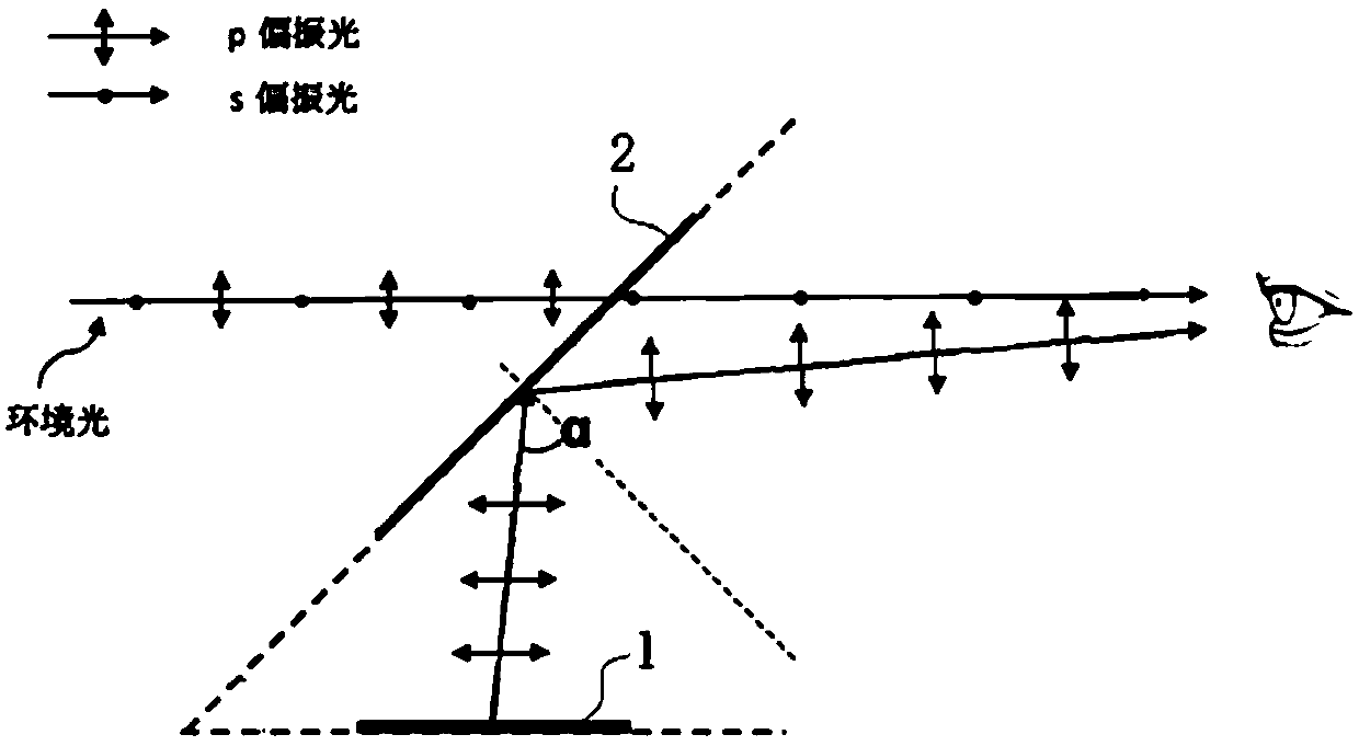
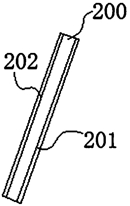
[0037] A kind of display system of this embodiment, refer to figure 1 , including an image source device 1 and a developing device 2, the light emitted by the image source device 1 reaches the developing device 2 and is reflected to the human eye through the developing device 2; the image source device 1 emits P-polarized light, and the light emitted by the image source device 1 The P-polarized light is incident on the imaging device 2 at a certain angle, and then reflected to human eyes through the imaging device 2 . refer to figure 2 , the imaging device 2 comprises a transparent substrate 200 and a polarized transflective film 201 disposed on the inner surface of the transparent substrate that reverses P polarized light and transmits S polarized light. The polarizing transflective film 201 is used to reflect the incident light of P polarized light to human eyes to form a virtual image, and the polarizing transflective film 201 that reverses P polarized light and transmits...
Embodiment 2
[0039] A display system of this embodiment is based on Embodiment 1, refer to figure 2 , the imaging device 2 includes an anti-reflection film 202, which is arranged on the outer surface of the transparent substrate 200, adopts a polarized transflective film that reverses P-polarized light and transmits S-polarized light, and the S-polarized light of external ambient light passes through The anti-P polarized light transmits the polarized transflective film of the S polarized light to the human eye, and the polarized transflective film for the anti-P polarized light and transmitted the S polarized light has a higher transmittance to the S polarized light of the external ambient light. Adding an anti-reflection film on the outer surface of the material can further increase the transmittance of the S-polarized light of the external ambient light, so that the driver can observe the displayed information more clearly and can see the external environment more clearly.
Embodiment 3
[0041] A display system in this embodiment is based on the second embodiment. The polarized transflective film that reverses P-polarized light and transmits S-polarized light is made of a polymer film, and the polarized transflective film that reverses P-polarized light and transmits S-polarized light is made of a similar polarized transflective film. The film layers with high and low refractive index changes between the adjacent film layers are stacked. The polarized transflective film that reverses P polarized light and transmits S polarized light made of polymer film has a reflectivity of 100% for P polarized light. The transmittance of S-polarized light in the external environment is over 50%, and the light efficiency is extremely high, which truly realizes the high transmittance and high reflection of the display system. See the external environment.
PUM
| Property | Measurement | Unit |
|---|---|---|
| reflectance | aaaaa | aaaaa |
| transmittivity | aaaaa | aaaaa |
Abstract
Description
Claims
Application Information
 - R&D
- Intellectual Property
- Life Sciences
- Materials
- Tech Scout
- Unparalleled Data Quality
- Higher Quality Content
- 60% Fewer Hallucinations
Browse by: Latest US Patents, China's latest patents, Technical Efficacy Thesaurus, Application Domain, Technology Topic, Popular Technical Reports.
© 2025 PatSnap. All rights reserved.Legal|Privacy policy|Modern Slavery Act Transparency Statement|Sitemap|About US| Contact US: help@patsnap.com


