A kind of wireless charging coil enameled wire with inner layer of magnetic nano ferrite material and preparation method thereof
A ferrite material and magnetic nanotechnology, applied in conductive materials, conductive materials, flexible cables, etc., can solve the problems of inability to fully improve the magnetoelectric conversion efficiency of wireless charging coils, unsafe hidden dangers, and low magnetostriction , to achieve the effects of increasing wireless charging efficiency, improving softness, and improving magnetism
- Summary
- Abstract
- Description
- Claims
- Application Information
AI Technical Summary
Problems solved by technology
Method used
Image
Examples
Embodiment 1
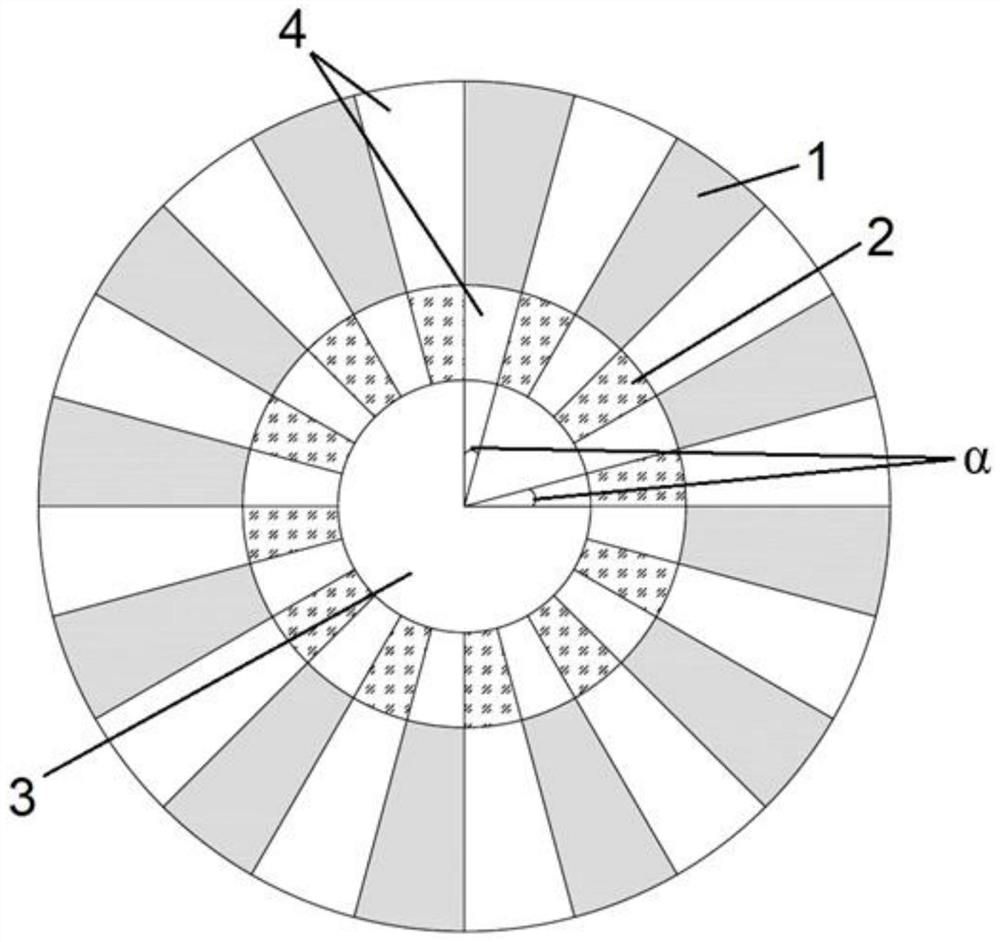
[0048] Such as figure 1 As shown, a structural diagram of a wireless charging coil in the inner layer of the magnetic nanoferder is provided in this example. The wireless charging coil enamel line is internally internally including inorganic insulating outer layer 1, conductive medium 2 and magnetic nanometers. The inner layer of the ferrite material; the inorganic insulating outer layer 1 and the conductive inner layer 2 hospiring are distributed on the outer circular arc of the magnetic nanoferder inner layer 3, and the interval distribution of the inorganic insulated outer layer 1 and the interval distribution of the conductive inner layer 2 Disconnecting each other, the angle α of the interval distribution is 15 °, and the interval distribution pore 4 is filled with an insulating material;
[0049] The inorganic insulated outer layer is an insulating polymer polymer polycycate;
[0050] Conductive middle layer is Fe 30 CO 50 B 10 Doped silver copper alloy;
[0051] Magnetic na...
Embodiment 2
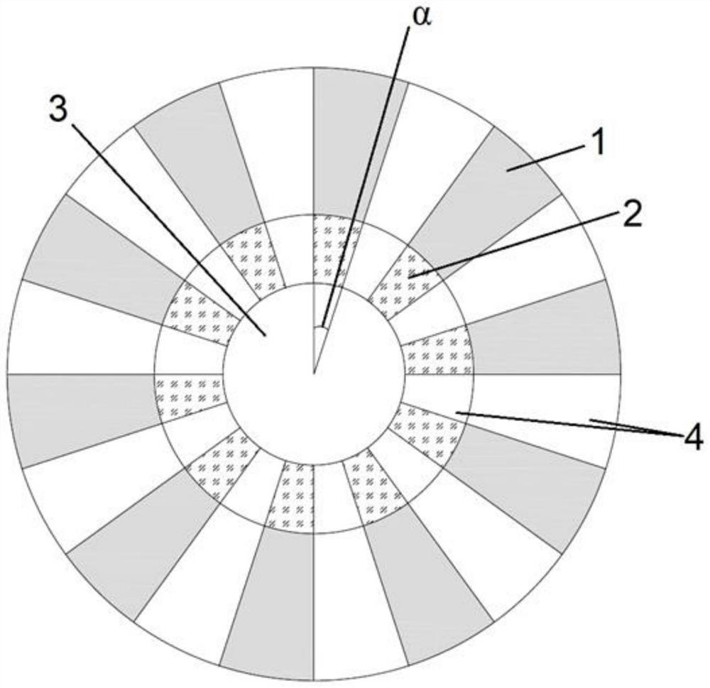
[0075] Such as figure 2 As shown, a structural diagram of a wireless charging coil in the inner layer of the magnetic nanoferder is provided in this example. The wireless charging coil enamel line is internally internally including inorganic insulating outer layer 1, conductive medium 2 and magnetic nanometers. The inner layer of the ferrite material; the inorganic insulating outer layer 1 and the conductive inner layer 2 hospiring are distributed on the outer circular arc of the magnetic nanoferder inner layer 3, and the interval distribution of the inorganic insulated outer layer 1 and the interval distribution of the conductive inner layer 2 The same, the angle α of the interval distribution is 18 °, and the interval distribution pore 4 is filled with an insulating material;
[0076] Inorganic insulated outer layer is an insulating polymer polymer polyamideimide;
[0077] Conductive middle layer is Fe 40 CO 30 B 20 Doped silver copper alloy;
[0078] Magnetic nanoferic material...
Embodiment 3
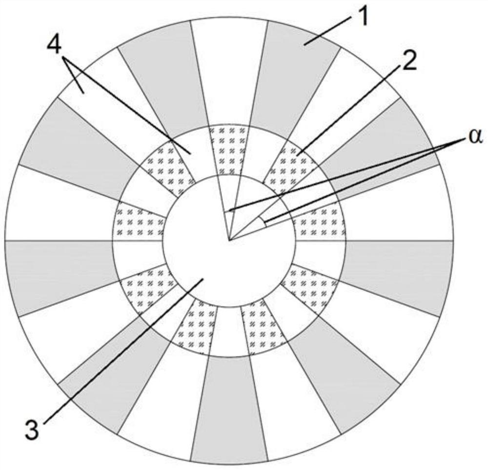
[0100] Such as image 3 As shown, a structural diagram of a wireless charging coil in the inner layer of the magnetic nanoferder is provided in this example. The wireless charging coil enamel line is internally internally including inorganic insulating outer layer 1, conductive medium 2 and magnetic nanometers. The inner layer of the ferrite material; the inorganic insulating outer layer 1 and the conductive inner layer 2 hospiring are distributed on the outer circular arc of the magnetic nanoferder inner layer 3, and the interval distribution of the inorganic insulated outer layer 1 and the interval distribution of the conductive inner layer 2 The angle α of the confusing, the interval distribution is 20 °, and the interval distribution pore 4 is filled with an insulating material;
[0101] The outer layer of inorganic insulated is ethyl polyacrylate;
[0102] Conductive middle layer is Fe 50 CO 40 B 30 Doped silver copper alloy;
[0103] Magnetic nanoferic material in the inner l...
PUM
| Property | Measurement | Unit |
|---|---|---|
| diameter | aaaaa | aaaaa |
Abstract
Description
Claims
Application Information
 - R&D
- Intellectual Property
- Life Sciences
- Materials
- Tech Scout
- Unparalleled Data Quality
- Higher Quality Content
- 60% Fewer Hallucinations
Browse by: Latest US Patents, China's latest patents, Technical Efficacy Thesaurus, Application Domain, Technology Topic, Popular Technical Reports.
© 2025 PatSnap. All rights reserved.Legal|Privacy policy|Modern Slavery Act Transparency Statement|Sitemap|About US| Contact US: help@patsnap.com


