Pretreatment device for mold machining

A mold processing and pretreatment technology, which is applied in lighting and heating equipment, dry cargo handling, filtering and screening, etc., can solve the problem of insufficient preheating of raw materials, achieve uniform heating, improve dispersion effect, and ensure uniformity

Inactive Publication Date: 2020-07-31
HANGZHOU FENGHENG ELECTROMECHANICAL
View PDF5 Cites 2 Cited by
  • Summary
  • Abstract
  • Description
  • Claims
  • Application Information

AI Technical Summary

Problems solved by technology

[0003] Some molds in the prior art preheat the raw materials during use, but some molds do not preheat the raw materials uniformly during use, and cannot achieve a good preheating effect. Therefore, it is necessary to design a A kind of mold processing uses pretreatment equipment to solve the above-mentioned technical problems

Method used


Image

  • Pretreatment device for mold machining
  • Pretreatment device for mold machining
  • Pretreatment device for mold machining

Examples


Embodiment 1

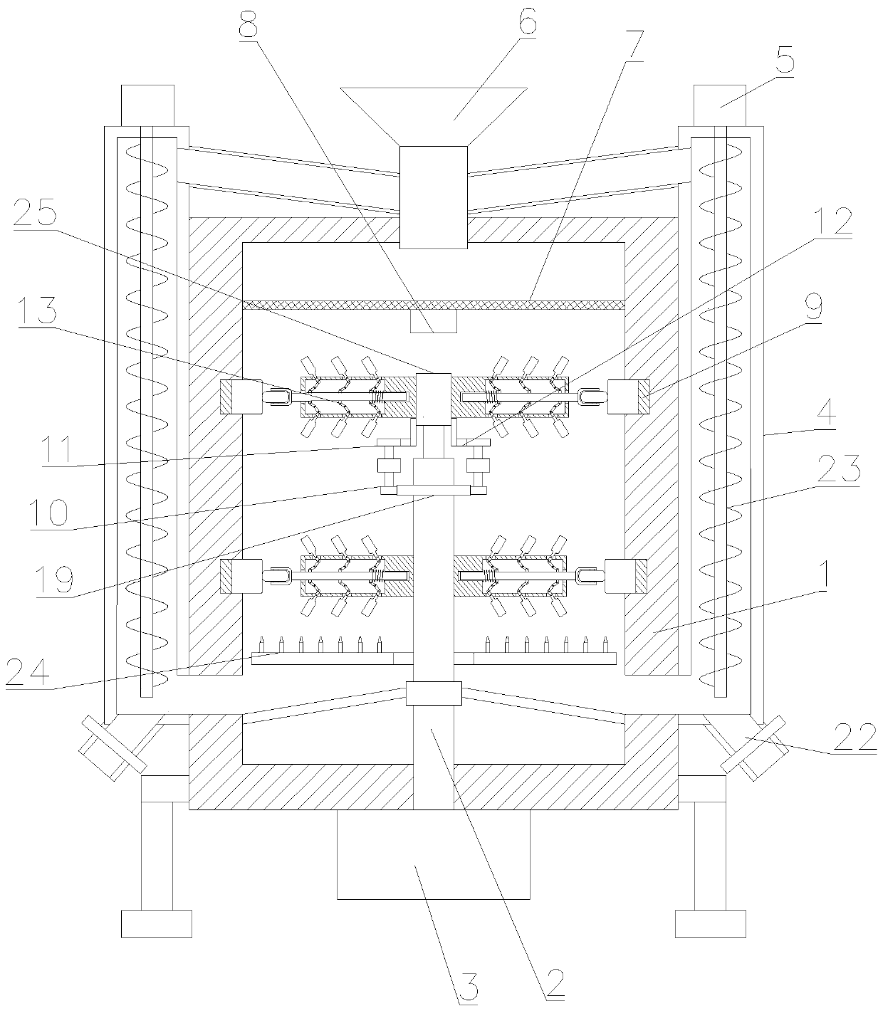
[0030] see Figure 1~4 , in Embodiment 1 of the present invention, a pretreatment device for mold processing, including a main body 1 with a cavity for dispersing and heating raw materials inside, and a distributing part, a dispersing part, and a heating part are arranged inside the main body 1 And arrange the circulation part 4 on both sides of the main body 1;

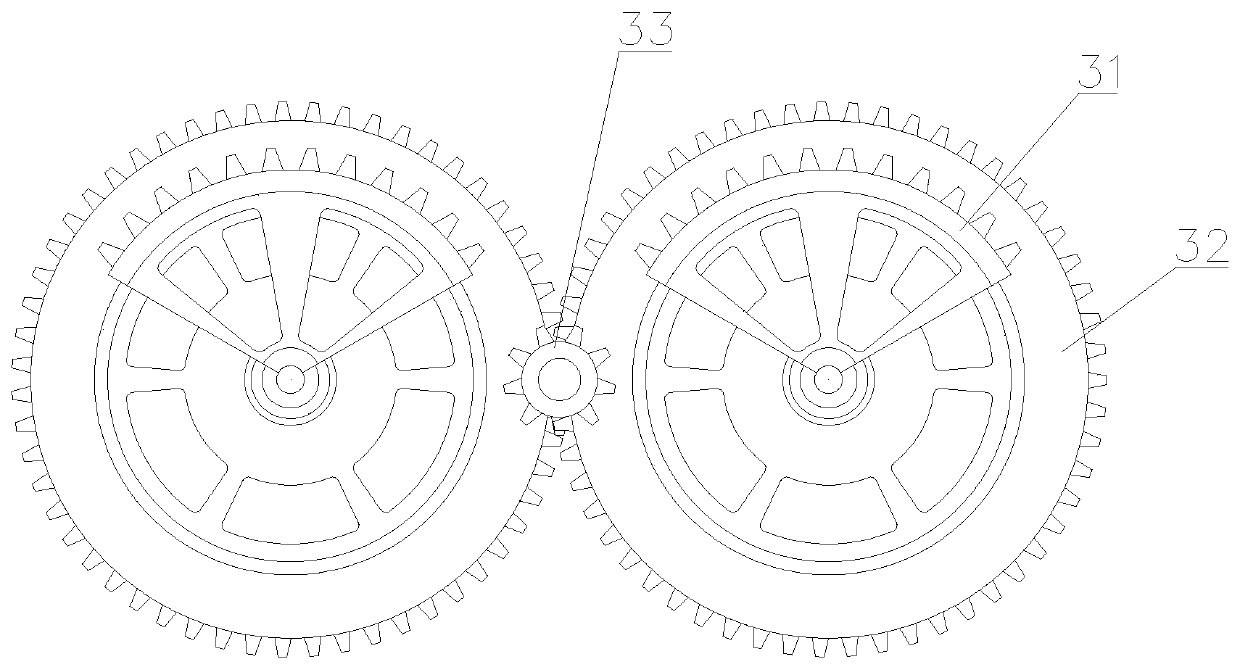
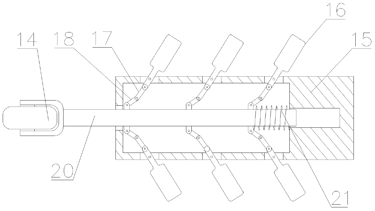
[0031] The dispersing part includes a rotating shaft 2 reciprocatingly arranged inside the main body 1. Two sets of mixing assemblies 13 rotating at a differential speed are arranged on the rotating shaft 2. Two sets of mixing assemblies 13 rotating at a differential speed are used to disperse materials at different speeds. , to improve the heating effect; the mixing assembly 13 includes a mixing piece 15 and a moving rod 20 slidingly arranged inside the mixing piece 15, and one end of the moving rod 20 protruding from the mixing piece 15 is fixedly installed with a driving ring that interferes with the inside of the...

Embodiment 2

[0033] see Figure 1~4 The main difference between the present embodiment 2 and the embodiment 1 is that the material distributing part includes a material distributing net 7 fixedly installed above the rotating shaft 2, and a vibrating motor 8 is arranged at the bottom of the distributing net 7, and the vibrating motor 8 drives the dispensing The net 7 vibrates up and down to disperse the material and improve the heating effect.

[0034] The heating component includes a gas delivery coil 24 fixed inside the main body 1 and a plurality of spray heads arranged in an array on the gas delivery coil 24, the nozzles communicate with the inside of the gas delivery coil 24, and the gas delivery The coil 24 is externally connected with heated air, and the air conveying coil 24 is arranged under the mixing assembly 13; the air conveying coil 24 is externally connected with heated air, and the falling material is heated through the nozzle.

[0035] A plurality of B connecting rods 18 a...


PUM


Abstract

The invention discloses a pretreatment device for mold machining, and relates to the technical field of mold machining equipment. The pretreatment device comprises a main body internally provided witha cavity for dispersing and heating raw materials, wherein a material distributing part, a dispersing part, a heating part and circulating parts arranged on the two sides of the main body are arranged in the main body; the dispersing part comprises a rotating shaft which is arranged in the main body in a reciprocating rotating mode, and two sets of mixing assemblies which rotate at different speeds are arranged on the rotating shaft; each mixing assembly comprises a mixing piece and a moving rod which is arranged in the mixing piece in a sliding mode, the end, protruding out of the mixing piece, of each moving rod is fixedly provided with a driving circular ring abutting against the interior of the main body, and the driving circular rings are fixedly arranged in the main body; and disturbance pieces which swing back and forth are arranged on the upper sides and the lower sides of the mixing assemblies. According to the pretreatment device, the materials are dispersed and heated in adisturbance mode, so that the heating uniformity is guaranteed.

Description

technical field [0001] The invention relates to the technical field of mold processing equipment, in particular to pretreatment equipment for mold processing. Background technique [0002] A mold is a tool used to shape an item. This tool is composed of various parts. It mainly realizes the processing of the shape of the item through the change of the physical state of the formed material. It is usually used in industry for injection molding, blow molding, and extrusion. , Die-casting or forging forming, smelting, stamping, stretching and other methods to obtain various molds and tools for the required products. [0003] Some molds in the prior art preheat the raw materials during use, but some molds do not preheat the raw materials uniformly during use, and cannot achieve a good preheating effect. Therefore, it is necessary to design a A kind of mold processing uses pretreatment equipment to solve the above-mentioned technical problems. Contents of the invention [0004...

Claims


Application Information

Patent Timeline
Patent Type & Authority Applications(China)
IPC IPC(8): B07B1/34B07B1/42B07B1/46F26B11/12F26B21/00F26B25/00F26B25/02F26B25/04
CPCB07B1/343B07B1/42B07B1/46F26B11/12F26B21/004F26B25/001F26B25/02F26B25/04
Inventor 孔磊姜乐明
Owner HANGZHOU FENGHENG ELECTROMECHANICAL
Why Eureka
Try Eureka