Energy saving system of air compressor

An energy-saving system, air compressor technology, applied in the direction of mechanical equipment, machines/engines, liquid variable capacity machinery, etc., can solve the problems of no protection mechanism, low safety in use, accelerated wear and tear of equipment, etc., to improve the safety of use Sex, avoid energy waste, reduce the effect of vibration frequency

Inactive Publication Date: 2020-07-31
广州宏创节能科技有限公司
View PDF5 Cites 1 Cited by
  • Summary
  • Abstract
  • Description
  • Claims
  • Application Information

AI Technical Summary

Problems solved by technology

[0002] The existing air compressor energy-saving control system is not installed with a shock-absorbing and noise-reducing mechanism. There is no protective mechanism installed on the energy-saving control system of the air compressor, and the operation button is installed at the front of the box, which can be easily touched by non-staff, which is easy to cause misoperation and low safety in use; in addition, most air compressors The compressor adopts a fixed-frequency motor, but due to the difference in the working cycle of the gas-consuming equipment or the production process and the uncertainty of the actual gas consumption, the air compressor with a fixed-frequency motor cannot automatically adjust the motor speed according to the value of the gas pressure. When the gas consumption is small, as the gas pressure increases, the unloading valve moves frequently, resulting in a great waste of electric energy and accelerated wear of the equipment

Method used

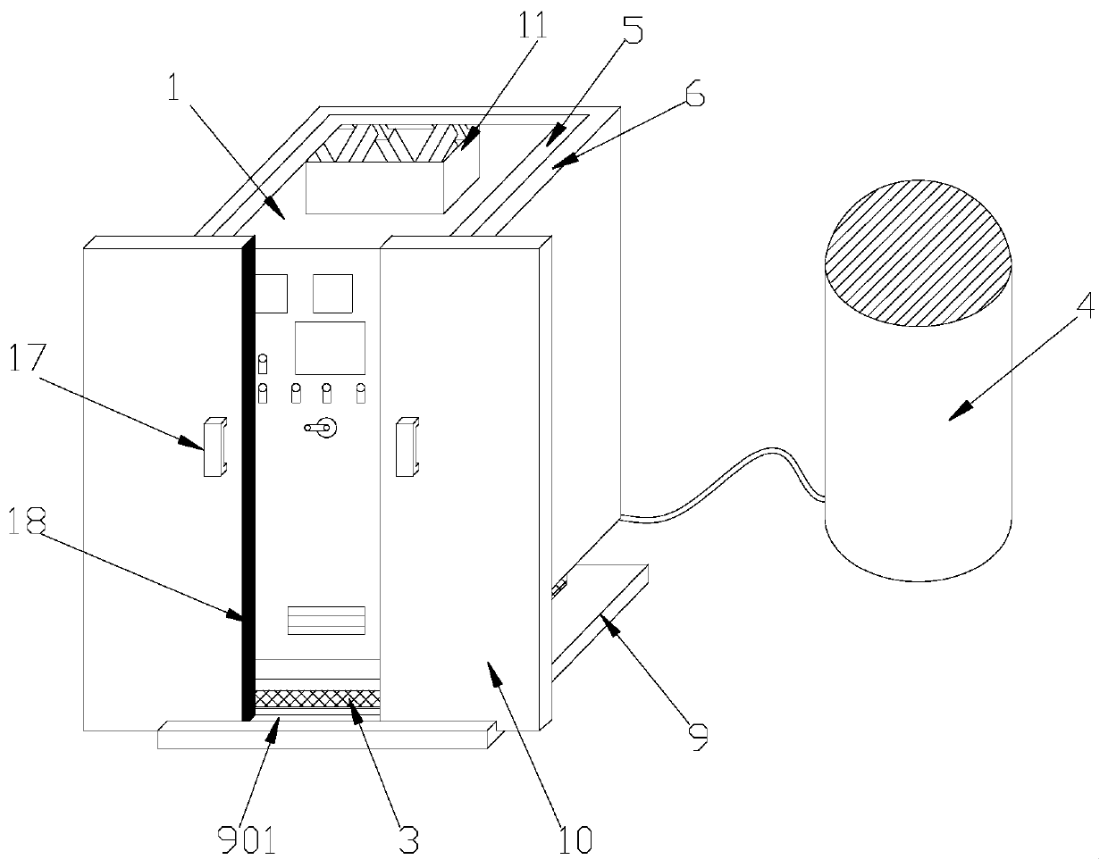
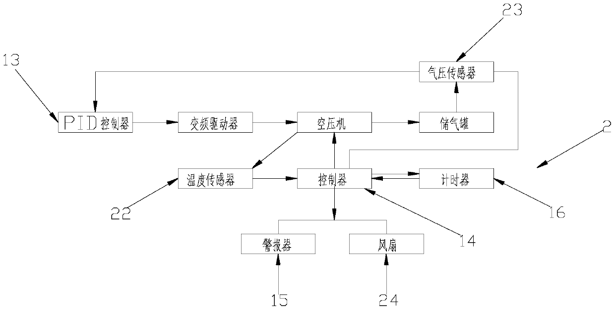
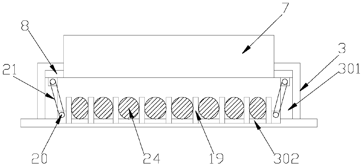

Image

  • Energy saving system of air compressor
  • Energy saving system of air compressor
  • Energy saving system of air compressor

Examples


Embodiment Construction

[0019] The following will clearly and completely describe the technical solutions in the embodiments of the present invention with reference to the accompanying drawings in the embodiments of the present invention. Obviously, the described embodiments are only some, not all, embodiments of the present invention. Based on the embodiments of the present invention, all other embodiments obtained by persons of ordinary skill in the art without making creative efforts belong to the protection scope of the present invention.

[0020] In the description of the present invention, it should be noted that the orientation or positional relationship indicated by the terms "vertical", "upper", "lower", "horizontal" etc. is based on the orientation or positional relationship shown in the drawings, and is only In order to facilitate the description of the present invention and simplify the description, it does not indicate or imply that the device or element referred to must have a specific o...


PUM


Abstract

The invention belongs to the technical field of air compressor systems, and particularly discloses an energy saving system of an air compressor. The energy saving system comprises an air compressor body, a control system, a fixed frame, an air storage tank, a sound absorption cotton layer and an elastic cotton layer. A bearing block is fixed to the bottom of the air compressor body and is in sliding connection with the inner wall of the fixed frame. A limiting sliding groove is formed in the inner wall of the fixed frame. Sliding blocks are fixed to the two sides of the bearing block and are in sliding connection with the limiting sliding groove. A bottom plate is fixed to the bottom of the fixed frame. A moving groove is formed in the bottom plate. Symmetric sealing doors are arranged inthe moving groove in a sliding manner, and the sealing doors are attached to the front face of the air compressor. An air outlet of the air compressor communicates with the air storage tank through anair guide pipe. A control cabinet is arranged at the top of the air compressor, and a PID controller, a frequency conversion driver, a controller, an alarm and a timer are arranged in the control cabinet.

Description

technical field [0001] The invention relates to an air compressor energy-saving system, which belongs to the technical field of air compressor systems. Background technique [0002] The existing air compressor energy-saving control system is not installed with a shock-absorbing and noise-reducing mechanism. There is no protective mechanism installed on the energy-saving control system of the air compressor, and the operation button is installed at the front of the box, which can be easily touched by non-staff, which is easy to cause misoperation and low safety in use; in addition, most air compressors The compressor adopts a fixed-frequency motor, but due to the difference in the working cycle of the gas-consuming equipment or the production process and the uncertainty of the actual gas consumption, the air compressor with a fixed-frequency motor cannot automatically adjust the motor speed according to the value of the gas pressure. When the gas consumption is small, as the...

Claims


Application Information

Patent Timeline
Patent Type & Authority Applications(China)
IPC IPC(8): F04B49/06F04B49/20F04B49/10F04B51/00F04B41/02F04B39/00F04B39/12F16F15/04
CPCF04B39/0033F04B39/0044F04B39/121F04B41/02F04B49/06F04B49/10F04B49/20F04B51/00F16F15/04
Inventor 吴军军姜楷庞森祥
Owner 广州宏创节能科技有限公司
Why Eureka
Try Eureka