a dimmer

A dimmer and optical path technology, applied in the field of dimmers, can solve the problems of inability to ensure long-term stable operation of the equipment, not meeting the moving target simulator, low transmittance of liquid crystal light valves, etc., to ensure long-term stable operation, The effect of high light efficiency utilization and long service life

Active Publication Date: 2021-10-19
哈尔滨新光光电科技股份有限公司
View PDF7 Cites 0 Cited by
  • Summary
  • Abstract
  • Description
  • Claims
  • Application Information

AI Technical Summary

Problems solved by technology

[0004] One purpose of the present invention is to solve the defects that the mechanical shutter cannot guarantee the long-term stable operation of the equipment when it works at a switching frequency of 200 Hz, and the liquid crystal light valve has low transmittance, low contrast, and does not meet the technical requirements of the moving target simulator.

Method used


Image

  • a dimmer
  • a dimmer
  • a dimmer

Examples


Embodiment 1

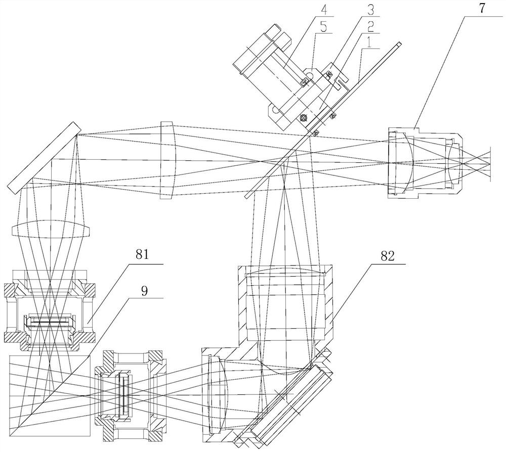
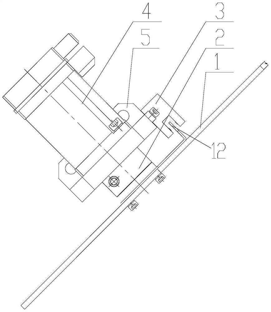
[0050] The structure of the dimmer in this embodiment is shown in FIG. 1 . Dimming disc 1 adopts the structure shown in Figure 2(a), and the size of the disc is designed according to the light-passing area. The disc is precisely processed by a diamond lathe, and has high surface precision and high reflectivity. The reflective optical path 82 works when 1 is cut into the optical path, and the transmissive optical path 81 works when the dimming disc 1 is cut out of the optical path. The disc 1 is connected to the servo motor 3 through the motor coupling 2, and the motor rotates once so that the reflected optical path 82 and the transmitted optical path 81 can work twice respectively, so setting the rotation frequency of the disc 1 to 50 Hz can achieve a frame frequency of 200 Hz. The servo motor 3 is used to drive the rotation frequency of 50 Hz corresponding to a speed of 3000 rpm, which is within the rated speed range of the servo motor 3 and can work for a long time. The pho...

Embodiment 2

[0053] On the basis of the hardware of Embodiment 1, the present embodiment further includes installing a digital I / O card, an analog DA card and an encoder card on the PCI bus of the control computer, for realizing the sampling and output of the control signal: wherein the digital The quantity I / O card receives the external synchronous signal and the pulse level of the feedback signal of the photoelectric switch, the analog quantity DA card can output the analog quantity voltage signal of -10V~+10V, the motor driver receives the analog quantity voltage signal and drives the motor at -3500rpm / The speed is regulated within the range of 1-3500 rpm, and a certain margin of speed regulation can be left to avoid synchronization failure caused by the frequency jitter of the input signal; the servo motor itself is equipped with an encoder, and the encoder card can detect the encoder feedback. Obtaining the position information of the current dimmer, one imaging device can meet the re...


PUM


Abstract

In order to solve the defects that the mechanical shutter cannot guarantee the long-term stable operation of the equipment, and the liquid crystal light valve has low transmittance, low contrast, and does not meet the technical requirements of the moving target simulator, a dimmer is proposed, including: a dimmer disc and a control mechanism, the control mechanism is used to control the rotation of the disc; the disc has a first area, and the first area is used to make the first area reflect on the surface of the first area when it cuts into the optical path of the light source. One light path is working; and when the light source light path is cut out, the light source light path misses the adjusting disc so that the second light path works. The present invention can meet the maximum frame frequency requirement of 200Hz; compared with mechanical shutters, it can ensure long-term stable operation and has a longer service life, and compared with liquid crystal light valves with lower transmittance, the present invention has higher reflectivity , high transmittance, and higher light efficiency utilization. The invention is applicable to the improvement of the moving target simulator.

Description

technical field [0001] The invention relates to the field of dynamic target simulator components, in particular to a dimmer. Background technique [0002] Visible light moving target simulator is the performance test equipment of visible light imaging guidance seeker, and also an important part of visible light imaging guidance hardware-in-the-loop simulation test system. Early moving target simulators generally only have a frame rate of 50Hz or 60Hz or a higher frame rate of 100Hz. As the frame rate of the seeker optical sensor continues to increase, the frame rate of the simulator also needs to be increased accordingly. This simulator requires To achieve a frame rate of 200Hz, the simulator cannot use large-size imaging devices due to volume limitations, and the highest frame rate of available imaging devices is only 100Hz. Therefore, in the design of this simulator, two imaging devices are used to work alternately to achieve 200Hz Therefore, it is necessary to design a d...

Claims


Application Information

Patent Timeline
Patent Type & Authority Patents(China)
IPC IPC(8): G02B26/04
CPCG02B26/04
Inventor 李长城
Owner 哈尔滨新光光电科技股份有限公司
Why Eureka
Try Eureka