
Road detection system and method under automatic tracking correction

An automatic tracking and road detection technology, applied in radio wave measurement systems, satellite radio beacon positioning systems, measurement devices, etc., can solve problems such as detection track deviation, low work sustainability, and impact on detection results

Active Publication Date: 2020-07-31
CHONGQING UNIV
View PDF4 Cites 3 Cited by
  • Summary
  • Abstract
  • Description
  • Claims
  • Application Information

AI Technical Summary

Problems solved by technology

This kind of traditional detection mainly relies on the driver's subjective control and GPS signal assistance in the detection of direction and speed control, which will require the driver to be highly concentrated for a long time during the detection process, and the detection has accuracy and There are a series of problems such as poor robustness, serious influence of human factors, low work sustainability, and inability to intelligently control the detection speed. Impact on final test results

Method used


Image

  • Road detection system and method under automatic tracking correction
  • Road detection system and method under automatic tracking correction
  • Road detection system and method under automatic tracking correction

Examples


Embodiment 1

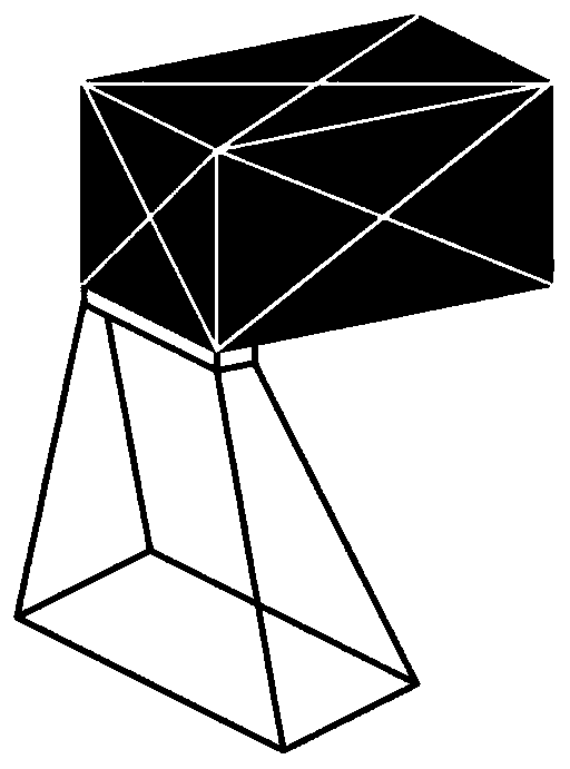
[0071] see Figure 1 to Figure 8, the road detection system under automatic tracking correction, mainly includes road defect detection vehicle, intelligent tracking module, intelligent speed regulation module, integrated control system, signal transceiver module, upper computer, GPS positioning module and power system.

[0072] The intelligent tracking module, intelligent speed regulation module, integrated control system, and signal transceiver module are mounted on the road defect detection vehicle and move with the vehicle.

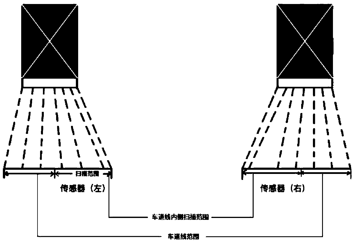
[0073] The intelligent tracking module is an infrared photoelectric sensor respectively pasted on both sides of the front of the road defect detection vehicle. The layout of the intelligent tracking module is as follows: figure 1 As shown, the sensor used is an 8-way infrared transceiver sensor (that is, there are 8 measuring points), the erection height is 50cm, the detection vehicle is 2m wide, the sensor scanning range is 15cm, and the distance bet...

Embodiment 2

[0112] The detection method based on the road detection system under automatic tracking correction mainly includes the following steps:

[0113] 1) Set the parameters of the road defect detection vehicle, mainly including the length of the road section to be tested, detection time and section speed.

[0114] 2) Put the road defect detection vehicle at the starting point of the road section to be tested, and start the road detection system under automatic tracking correction.

[0115] 3) The intelligent tracking module monitors the driving track of the road defect detection vehicle. The intelligent tracking module is an infrared receiver attached to the left and right sides of the road defect detection vehicle. The number of infrared receivers on the left and right sides of the road defect detection vehicle is n, and n is an even number.

[0116] During monitoring, two intelligent tracking modules radiate infrared light to the road directly in front of the road defect detecti...


PUM


Abstract

The invention discloses a road detection system and method under automatic tracking correction. The system comprises a road defect detection vehicle, an intelligent tracking module, an intelligent speed regulation module, an integrated control system, a signal transceiving module and an upper computer, the method comprises the following steps: 1) a road detection system under automatic tracking correction is started; 3) the intelligent tracking module monitors the driving track of the road defect detection vehicle; the intelligent speed regulation module monitors the three-dimensional acceleration of the road defect detection vehicle; and (4) the integrated control system is used for judging the driving position of the road defect detection vehicle in real time, so that the problems of detection result deviation, unstable detection, poorer deviation correction real-time performance, low detection efficiency and the like caused by subjective influence factors of driver driving in the traditional road detection process are effectively solved.

Description

technical field [0001] The invention relates to the field of road detection, in particular to a road detection system and method under automatic tracking correction. Background technique [0002] The transportation network is an important link to promote economic development. With the progress of the society and the rapid development of the economic level, roads, which are one of the important components of the transportation network, have also developed rapidly. And so it came. How to effectively detect road diseases and carry out scientific maintenance to prolong its service life has also become an important issue. The traditional road surface detection method mainly uses the road defect detection vehicle as the equipment platform, relies on the driver to drive the detection vehicle on the road to be tested, and identifies road surface defects with the help of the detection equipment on the detection vehicle. This kind of traditional detection mainly relies on the drive...

Claims


Application Information

Patent Timeline
IPC IPC(8): G06K9/00G06K9/62G01P15/18G01S19/42
CPCG01P15/18G01S19/42G06V20/588G06F18/24
Inventor 陈鹏举王慧
Owner CHONGQING UNIV
Learn More