
Iron-based amorphous iron core production system and preparation method thereof

A production system, iron-based amorphous technology, applied in the manufacture of stator/rotor bodies, etc., can solve problems that affect the yield of iron cores, easily damage amorphous blocks, and are difficult to detect in time

Pending Publication Date: 2020-07-31
宁波吉兆电气科技有限公司
View PDF0 Cites 1 Cited by
  • Summary
  • Abstract
  • Description
  • Claims
  • Application Information

AI Technical Summary

Problems solved by technology

The second is the superimposed punching method: select a sheet of appropriate width, cut it into a punched sheet of a specified size and shape by punching, then stack the punched sheet to a specified height, eliminate the internal stress through the annealing process, and pass through the resin after annealing. The dipping and solidification casting process makes the stacking of the stator punches into a whole to form an amorphous core; the main problem with the first method is that after the amorphous material is superimposed into an amorphous block, the thickness increases greatly, and the amorphous core is easily damaged during cutting. Crystal blocks, resulting in gaps, cracks, etc. on the edge of the cut iron core, and a high reject rate of the product; and the second method, the sheet is first cut into punched pieces, and then the punched pieces are superimposed into the production method of the iron core , although the damage rate in the cutting process is reduced, but because the amorphous nanocrystalline alloy material has the characteristics of "thin, hard and brittle", it is extremely difficult to process and shape it.
The stamping process adopted by the silicon steel core cannot be used universally due to the characteristics of the amorphous material; for example, laser cutting, plasma cutting, flame cutting, EDM cutting and other means of cutting through hot melting will cause the amorphous and nanocrystalline materials to be heated and crystallized, thereby destroying The original soft-testing characteristics of the material; therefore, the application of the stamping superposition method in amorphous and nanocrystalline materials is limited. In addition, the annealing operation of the traditional process is often set after the superposition molding, and during production, because the amorphous coil is not The single-layer structure is composed of several thinner amorphous materials, which makes it difficult to find defective materials in time due to the composite of amorphous materials, which affects the yield of the iron core and causes a lot of waste of raw materials.

Method used

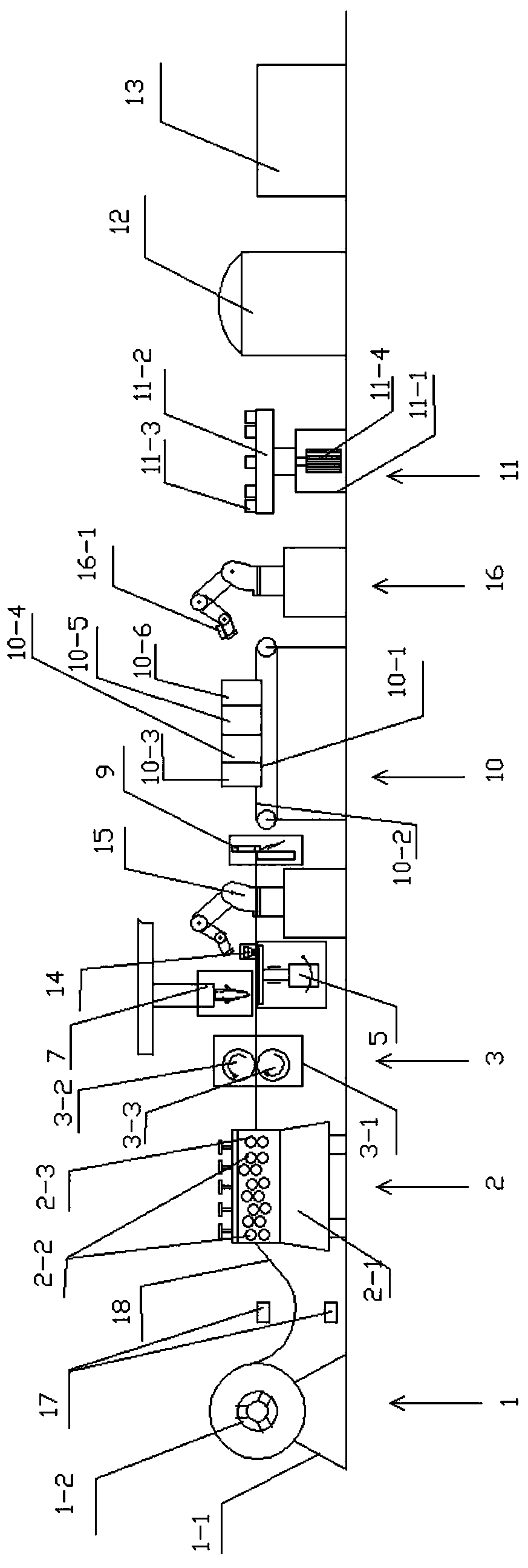

Image

  • Iron-based amorphous iron core production system and preparation method thereof
  • Iron-based amorphous iron core production system and preparation method thereof
  • Iron-based amorphous iron core production system and preparation method thereof

Examples


Embodiment Construction

[0055] The technical solutions of the present invention will be clearly and completely described below in conjunction with the accompanying drawings. Apparently, the described embodiments are some of the embodiments of the present invention, but not all of them. Based on the embodiments of the present invention, all other embodiments obtained by persons of ordinary skill in the art without making creative efforts belong to the protection scope of the present invention.

[0056] In the description of the present invention, it should be noted that the terms "center", "upper", "lower", "left", "right", "vertical", "horizontal", "inner", "outer" etc. The indicated orientation or positional relationship is based on the orientation or positional relationship shown in the drawings, and is only for the convenience of describing the present invention and simplifying the description, rather than indicating or implying that the referred device or element must have a specific orientation, ...


PUM


Abstract

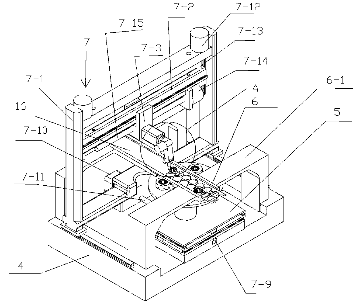
The invention relates to an iron-based amorphous iron core production system and a preparation method thereof. The system comprises a discharging mechanism, a leveling mechanism, a feeding mechanism,a jet flow cutting device, a waste recycling mechanism, a tunnel type annealing furnace, a forming overlying mechanism, a gum dipping device and a curing oven which are sequentially arranged from leftto right in the conveying direction. A workpiece cleaning device and a first transfer robot are arranged between the jet cutting mechanism and the waste recovery mechanism, and the cleaning device and the first transfer robot are arranged on the two sides of a strip correspondingly; and a second transfer robot is arranged between the tunnel type annealing furnace and the forming overlying mechanism. Continuous production of the iron core is achieved, annealing and forming stacking are conducted in sequence, defective punching sheets can be found earlier, and the defective rate of finished products is reduced.

Description

technical field [0001] The invention belongs to the field of motor preparation, and in particular relates to an iron-based amorphous iron core production system and a preparation method thereof. Background technique [0002] There are currently two manufacturing techniques for motor iron cores. The first is the amorphous block cutting method: first, the amorphous alloy strip (18) of a predetermined width is cut to form an amorphous sheet of a specified length, and the amorphous sheet is superimposed on the specified length. Thickness forms an amorphous block (amorphous rod), and then undergoes a certain annealing process to eliminate internal stress, and finally cuts to form an amorphous core of the size and shape specified in the drawing. The second is the superimposed punching method: select a sheet of appropriate width, cut it into a punched sheet of a specified size and shape by punching, then stack the punched sheet to a specified height, eliminate the internal stress t...

Claims


Application Information

Patent Timeline
IPC IPC(8): H02K15/02
CPCH02K15/02
Inventor 王晶
Owner 宁波吉兆电气科技有限公司
Learn More