
A heating control method for a liquid supply pump

A liquid supply and heating control technology, applied in the components of pumping devices for elastic fluids, liquid fuel engines, pump elements, etc., can solve the problems of many layout limits, protection, and increase of leakage points in the cooling system of the whole vehicle. , to achieve stable and reliable work and ensure the effect of heating speed

Active Publication Date: 2022-05-27
KAILONG HIGH TECH
View PDF7 Cites 0 Cited by
  • Summary
  • Abstract
  • Description
  • Claims
  • Application Information

AI Technical Summary

Problems solved by technology

The liquid heating method has the disadvantages of complicated liquid pipeline connection, many layout limits, and increased leakage points of the vehicle cooling system
Electric heating is often controlled by a switch, and the heating power is not adjusted; after the heating is completed, no insulation measures are taken to prevent the liquid supply pump from freezing again; in addition, there is no protection for the power supply of the vehicle

Method used


Image

  • A heating control method for a liquid supply pump
  • A heating control method for a liquid supply pump
  • A heating control method for a liquid supply pump

Examples


Embodiment Construction

[0028] The present invention will be further described below with reference to the accompanying drawings and embodiments. It should be understood that the specific embodiments described herein are only used to explain the present invention, but not to limit the present invention. In addition, it should be noted that, for the convenience of description, the drawings only show part but not the whole content related to the present invention. Unless otherwise defined, all technical and scientific terms used herein are related to the technical field of the present invention. The same meaning is generally understood by the skilled person. The terminology used herein is for the purpose of describing specific embodiments only and is not intended to limit the invention.

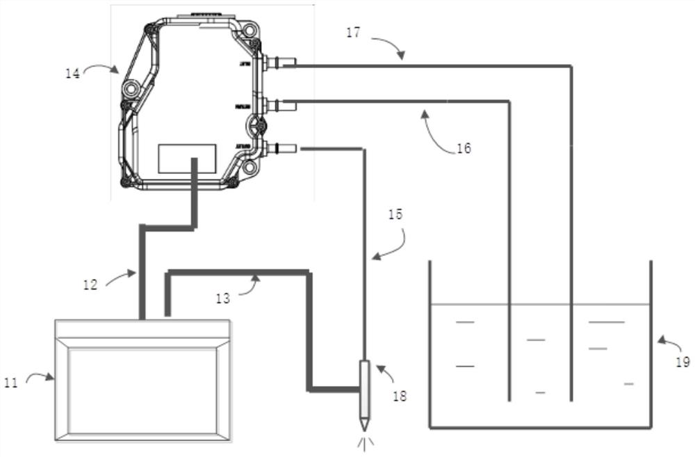
[0029] Please refer to figure 1 shown, figure 1 Schematic diagram of components of diesel engine aftertreatment urea injection system. The diesel engine post-treatment urea injection system includes diesel control...


PUM


Abstract

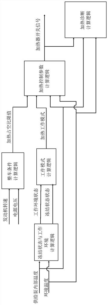
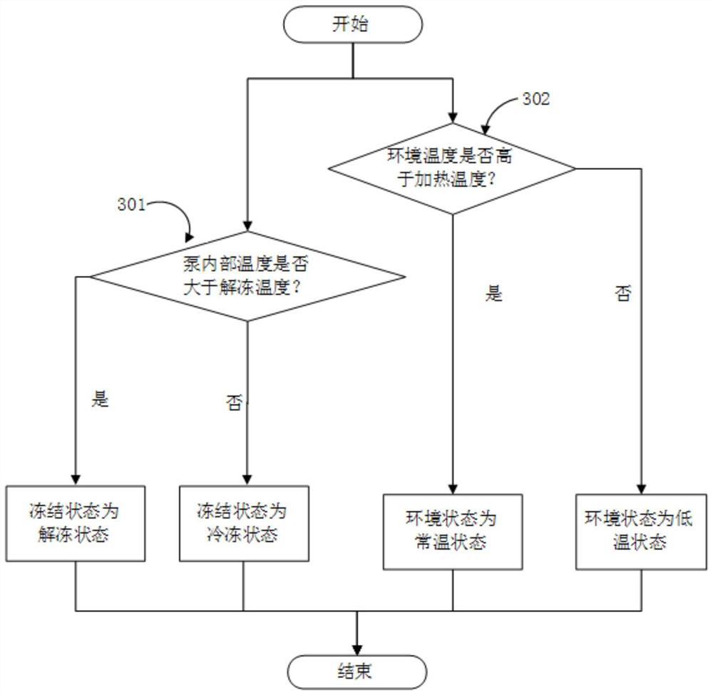
The invention discloses a heating control method of a liquid supply pump. The method comprises the following steps: judging the freezing state of the liquid in the liquid supply pump by using an internal temperature sensor of the liquid supply pump; According to the working environment state of the liquid supply pump; calculate the heating mode that the liquid supply pump needs to enter according to the freezing state of the liquid in the liquid supply pump and the working environment of the liquid supply pump; according to the heating mode of the liquid supply pump, use the power supply for the liquid supply pump The voltage calculation is suitable for the defrost control parameters of the liquid supply pump; the diagnosis is made according to the internal temperature rise characteristics of the liquid supply pump. According to the frozen state of the liquid in the liquid supply pump and its environment, the present invention can calculate appropriate control parameters to perform thawing or heat preservation control, so that the liquid supply pump can work stably and reliably in cold environments.

Description

technical field [0001] The invention relates to the field of after-treatment of internal combustion engines, in particular to a heating control method for a liquid supply pump. Background technique [0002] Diesel engine has the characteristics of high economy, strong power and long service life, and is one of the most used power sources for transportation vehicles today. Due to its wide range of applications, it has also become one of the main emission sources of air pollutants such as particulate pollutants and nitrogen oxides. Only relying on the improvement of the diesel engine itself can no longer meet the current and future emission regulations in my country. The installation of a selective catalytic reduction system (SCR) for diesel engines is the current mainstream exhaust gas purification solution. In this system, the liquid supply pump is used to suck out the liquid reducing agent (urea solution with a certain concentration) from the storage tank, pressurize it t...

Claims


Application Information

Patent Timeline
Patent Type & Authority Patents(China)
IPC IPC(8): F01N3/20F04B53/08
CPCF01N3/208F01N3/2013F04B53/08
Inventor 马涛臧志成曾伟马超董孝虎
Owner KAILONG HIGH TECH
Learn More