IGBT dynamic parameter test circuit stray capacitance extraction method and system

A technology for testing circuits and dynamic parameters, which is applied in the direction of measuring resistance/reactance/impedance, measuring electricity, and capacitance measurement, etc. It can solve problems such as current distortion, affecting device parameter test results, and being unable to obtain stray capacitance in the IGBT test circuit. Achieve accurate measurement results

Active Publication Date: 2020-08-04
GLOBAL ENERGY INTERCONNECTION RES INST CO LTD
View PDF11 Cites 5 Cited by
  • Summary
  • Abstract
  • Description
  • Claims
  • Application Information

AI Technical Summary

Problems solved by technology

[0004] In view of this, the embodiment of the present invention provides a method and system for extracting stray capacitance of an IGBT dynamic parameter test circuit, which solves the current distortion caused by the rapid chang

Method used


Image

  • IGBT dynamic parameter test circuit stray capacitance extraction method and system
  • IGBT dynamic parameter test circuit stray capacitance extraction method and system
  • IGBT dynamic parameter test circuit stray capacitance extraction method and system

Examples


Embodiment 1

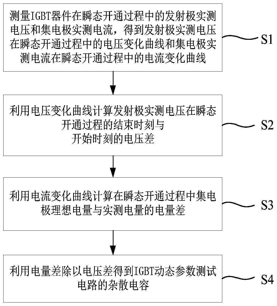
[0044] An embodiment of the present invention provides a method for extracting stray capacitance from an IGBT dynamic parameter test circuit, wherein the IGBT dynamic parameter test circuit is used to connect the IGBT device to test the IGBT device, such as figure 1 As shown, the IGBT dynamic parameter test circuit stray capacitance extraction method of the embodiment of the present invention includes the following steps:

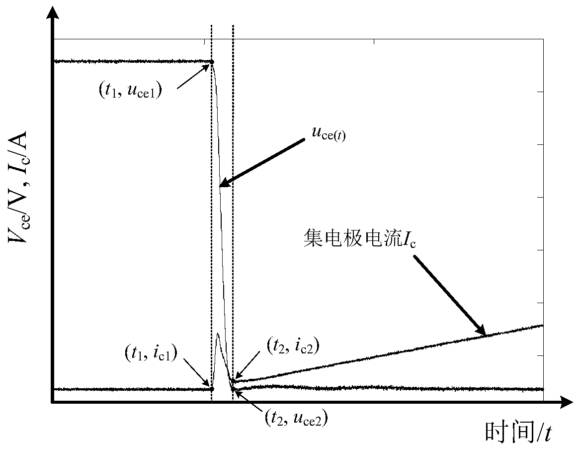
[0045] Step S1: Measure the actual emitter voltage and collector current of the IGBT device during the transient turn-on process, and obtain the voltage variation curve of the emitter actual voltage during the transient turn-on process and the collector current during the transient turn-on process. Current change curve.

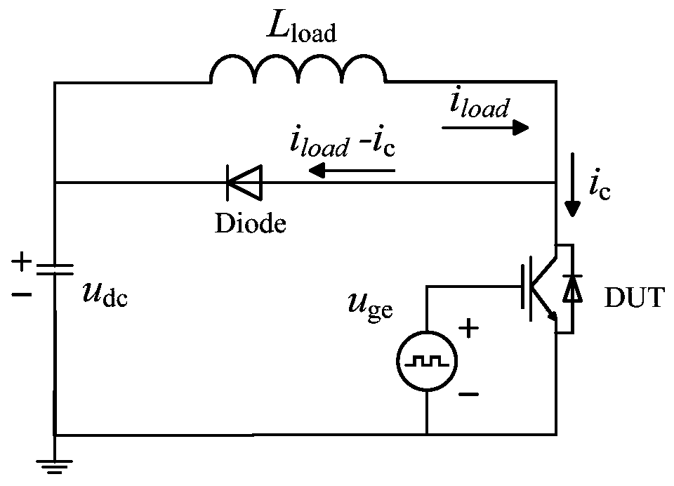
[0046] In the embodiment of the present invention, based on the double-pulse test method, an IGBT dynamic parameter test platform is built, and the test circuit schematic diagram is as follows figure 2 Shown, where, DUT is the device und...

Embodiment 2

[0091] The embodiment of the present invention provides a kind of IGBT dynamic parameter test circuit stray capacitance extraction system, such as Figure 5 shown, including:

[0092] The acquisition module 1 is used to measure the emitter actual voltage and the collector current during the transient turn-on process of the IGBT device, and obtain the voltage change curve of the emitter actual voltage during the transient turn-on process and the collector current during the transient turn-on. The current change curve during the process; this module executes the method described in step S1 in Embodiment 1, which will not be repeated here.

[0093] The first calculation module 2 is used to calculate the voltage difference between the actual measured voltage of the emitter at the end moment and the start moment of the transient opening process by using the voltage change curve; this module executes the method described in step S2 in Embodiment 1, which is not described here Let m...

Embodiment 3

[0098] An embodiment of the present invention provides an electronic device, such as Figure 6 As shown, it includes: at least one processor 401 , such as a CPU (Central Processing Unit, central processing unit), at least one communication interface 403 , memory 404 , and at least one communication bus 402 . Wherein, the communication bus 402 is used to realize connection and communication between these components. Wherein, the communication interface 403 may include a display screen (Display) and a keyboard (Keyboard), and the optional communication interface 403 may also include a standard wired interface and a wireless interface. The memory 404 may be a high-speed RAM memory (Ramdom Access Memory, volatile random access memory), or a non-volatile memory (non-volatile memory), such as at least one disk memory. Optionally, the memory 404 may also be at least one storage device located away from the aforementioned processor 401 . The processor 401 can execute the method for ...


PUM


Abstract

The invention discloses an IGBT dynamic parameter test circuit stray capacitance extraction method and system. The method comprises the following steps: measuring an emitter actual measurement voltageand a collector actual measurement current of an IGBT device in a transient switching-on process to obtain a voltage change curve of the emitter actual measurement voltage in the transient switching-on process and a current change curve of the collector actual measurement current in the transient switching-on process; calculating a voltage difference between an end moment and a start moment of the emitter actual measurement voltage in the transient switching-on process by using the voltage change curve; calculating an electric quantity difference between an ideal electric quantity of a collector and an actual measurement electric quantity in the transient switching-on process by utilizing the current change curve; and acquiring the stray capacitance of an IGBT dynamic parameter test circuit by dividing the voltage difference by the electric quantity difference. The stray capacitance of the dynamic test platform is calculated through an actual measurement method based on a switching-ontransient waveform of the IGBT device, accuracy of a measurement result of the dynamic test equipment can be effectively evaluated, and a basis is provided for formulating the standard of the stray capacitance of the equipment.

Description

technical field [0001] The invention relates to the technical field of device testing, in particular to a method and system for extracting stray capacitance of an IGBT dynamic parameter testing circuit. Background technique [0002] IGBT combines the advantages of MOS devices and bipolar transistor devices, and has become a mainstream device in the field of power electronics. It is widely used in communications, transportation, industry, and power transmission. The corresponding packaging structure has been developed by traditional Common welding type, developing towards ultra-low parasitic inductance package, intelligent power module and ultra-high power crimp package structure. [0003] IGBT dynamic parameters are the basic parameters to characterize the switching characteristics of IGBT and the basis of device application design. In order to measure the dynamic parameters of IGBT devices, it is necessary to build a corresponding dynamic performance test platform. Due to ...

Claims


Application Information

Patent Timeline
IPC IPC(8): G01R31/26G01R27/26
CPCG01R31/2608G01R31/2617G01R27/2605
Inventor 唐新灵滕乐天吴军民韩荣刚石浩金锐张喆林仲康王亮
Owner GLOBAL ENERGY INTERCONNECTION RES INST CO LTD
Why Eureka
Try Eureka