Direct current leakage protection method
A technology of DC leakage and leakage current, which is applied in the direction of protection that responds to fault currents, emergency protection circuit devices, emergency protection devices that automatically disconnect, etc., can solve the problems of large volume, easy interference, and high production cost. Achieve the effects of improving timeliness and accuracy, high reliability, and reducing engineering workload
- Summary
- Abstract
- Description
- Claims
- Application Information
AI Technical Summary
Problems solved by technology
Method used
Image

Examples
Embodiment 1
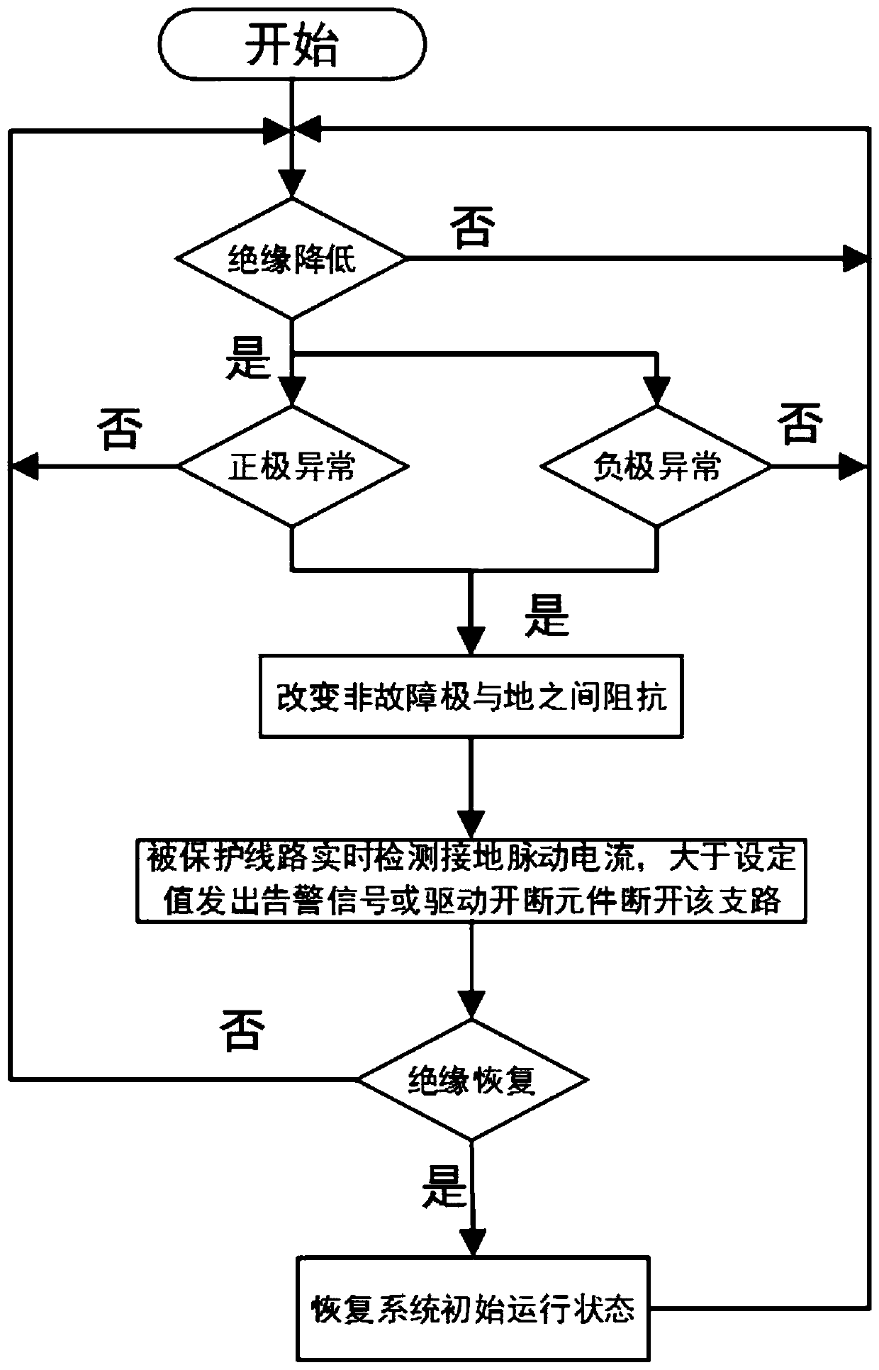
[0030] Such as figure 1 As shown, a DC leakage protection method, the above-mentioned protection method is applied to an ungrounded system or a high-impedance grounded system, and specifically includes the following steps:
[0031] (1) Determine whether the insulation resistance of the DC bus has decreased or the ground fault has occurred by detecting the insulation resistance of the DC bus to the ground (use the balance bridge resistance measurement method on the positive and negative buses of the DC power supply to detect the resistance of the DC bus to the ground. When the resistance of an electrode to the ground is less than the set value, it is judged that the electrode has a decrease in insulation resistance or a ground fault). The CPU controls the driving circuit, intermittently or periodically disconnects the IGBT to realize the intermittent or periodic change of the resistance between the DC bus (non-faulty pole) and the ground), and changes the distance between the o...
Embodiment 2
[0036] Such as figure 1 As shown, a DC leakage protection method, the above-mentioned protection method is applied to an ungrounded system or a high-impedance grounded system, and specifically includes the following steps:
[0037] (1) By detecting the insulation resistance of the DC bus to the ground, it is judged whether the insulation resistance of the DC bus has decreased or the ground fault has occurred (use the unbalanced bridge resistance measurement method on the positive and negative DC power supply bus to detect the resistance of the DC bus to the ground, when the DC bus When the ground resistance of one electrode or two electrodes is less than the set value, it is judged that the insulation resistance of the electrode or both poles of the DC bus bar has decreased or the ground fault has occurred);
[0038] When it is detected that there is a decrease in insulation resistance or a ground fault in a certain pole of the DC bus (when the CPU detects that the fault signa...
Embodiment 3
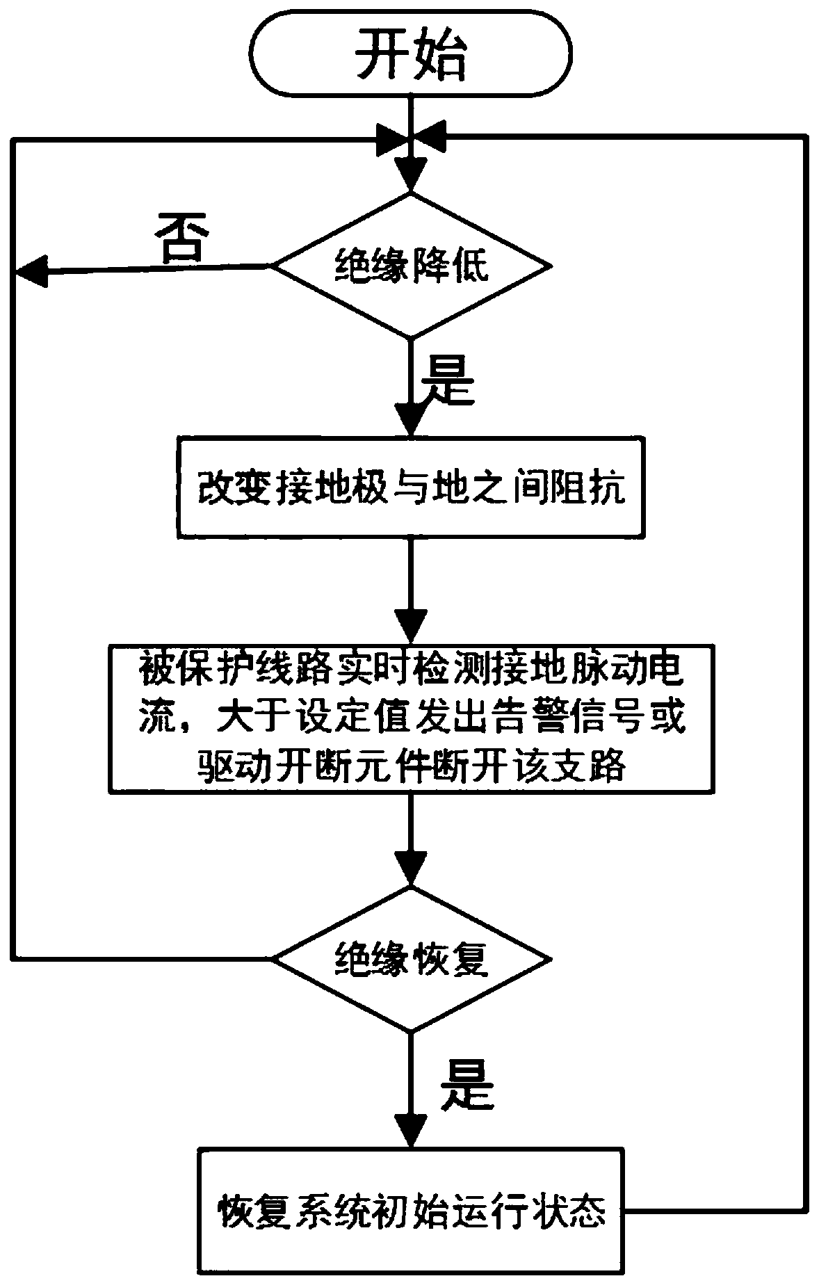
[0044] Such as figure 2 As shown, a DC leakage protection method, the above-mentioned protection method is applied in the grounding system, specifically includes the following steps:
[0045] (1) In the grounding system, the current sensor on the grounding line is used to detect the current on the grounding line of the DC power supply, so as to determine whether there is a decrease in insulation resistance or a grounding fault on the DC bus. When the resistance decreases or there is a ground fault, disconnect the grounding wire between the original grounding electrode and the earth (there is a switch on the grounding wire). input impedance device ( Figure 4 device, so that the grounding electrode is in the cycle of grounding and non-grounding, when the positive is grounded, the negative is not grounded, and when the negative is grounded, the positive is not grounded), inducing a pulsating leakage current between the fault point and the ground;
[0046] (2) Use the electrom...
PUM
 Abstract
Description
Claims
Application Information
 - R&D
- Intellectual Property
- Life Sciences
- Materials
- Tech Scout
- Unparalleled Data Quality
- Higher Quality Content
- 60% Fewer Hallucinations
Browse by: Latest US Patents, China's latest patents, Technical Efficacy Thesaurus, Application Domain, Technology Topic, Popular Technical Reports.
© 2025 PatSnap. All rights reserved.Legal|Privacy policy|Modern Slavery Act Transparency Statement|Sitemap|About US| Contact US: help@patsnap.com