
A ray tracing method

A ray tracing and ray technology, applied in the field of ray tracing, can solve problems such as increasing ray traversal time, achieve the effect of reducing the number of ray launches, reducing complexity, and improving speed

Active Publication Date: 2021-08-17
陈亮
View PDF6 Cites 0 Cited by
  • Summary
  • Abstract
  • Description
  • Claims
  • Application Information

AI Technical Summary

Problems solved by technology

However, the above improvement techniques all emit many rays, which increases the traversal time of rays in the scene

Method used


Image

  • A ray tracing method
  • A ray tracing method
  • A ray tracing method

Examples


Embodiment 1

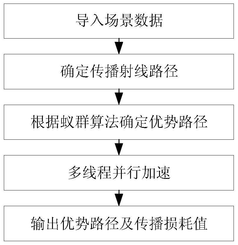
[0044] A ray tracing method, see figure 1 , the method includes the following steps:

[0045] Step 101: import scene data, and determine the propagation ray path;

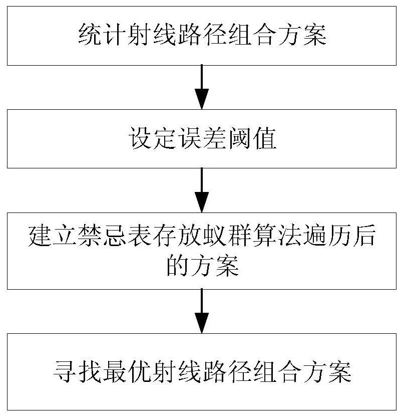
[0046] Step 102: See figure 2 , according to the ant colony algorithm to obtain the dominant path in the propagation ray path, the specific steps are as follows:

[0047] 1) According to the ant colony algorithm statistical advantage ray path combination scheme;

[0048] 2) Establish a taboo table to store the dominant ray path combination scheme after the ant colony algorithm traversal;

[0049] 3) Find the optimal ray path combination scheme in the tabu table.

[0050] Step 103: setting an error threshold;

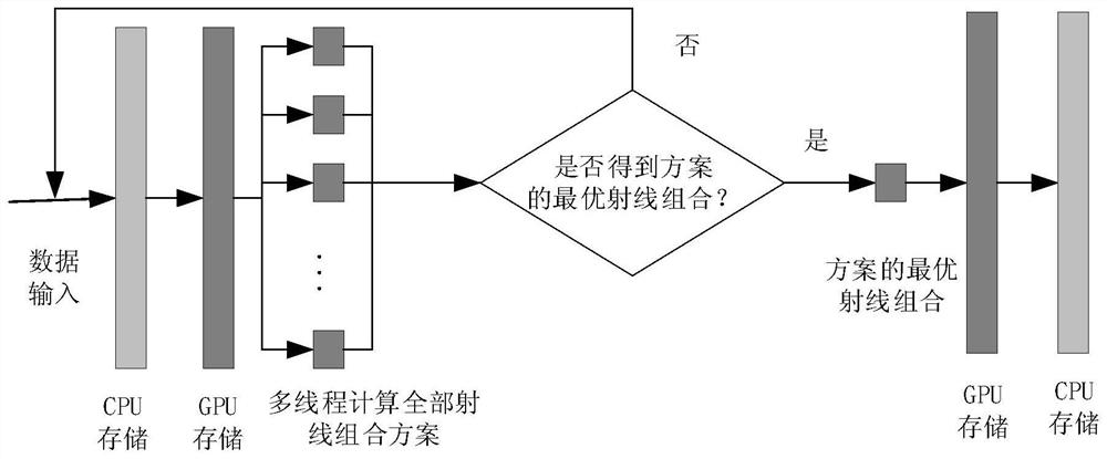
[0051] Step 104: See image 3 , multi-thread parallel acceleration, and output the optimal ray path and propagation loss value under the premise of meeting the error threshold.

Embodiment 2

[0053] Combine below Figure 1 to Figure 8 The scheme in Example 1 is further introduced, see the following description for details:

[0054] Step A: Comprehensively consider various communication application scenarios, use modeling tools to carry out three-dimensional modeling of the measured scene, count the materials in the scene environment and their electromagnetic parameters such as relative permittivity and magnetic permeability, and import them into electromagnetic simulation software or programming software Perform modeling simulations. Such as Figure 4 , Figure 5 As shown, build the indoor environment model:

[0055] Table 1 Electromagnetic parameters of different materials in indoor environment

[0056] material Permeability Relative permittivity thickness floor and ceiling 0.01 9 15.0 wall 0.01 9 10.0 Door 10 -5

13 4.0 table 10 -5

13 2.0 window 10 -12

7.6 1.0

[0057] Table 2 Antenna parame...


PUM


Abstract

The invention discloses a ray tracing method. The method comprises the following steps: importing scene data, determining the propagation ray path; obtaining a dominant path in the propagation ray path according to the ant colony algorithm; setting an error threshold; multi-thread parallel acceleration, in Under the premise of satisfying the error threshold, the optimal ray path and the propagation loss value are output; wherein, the acquisition of the dominant path in the propagation ray path according to the ant colony algorithm is specifically: according to the ant colony algorithm statistical advantage ray path combination scheme; The dominant ray path combination scheme after ant colony algorithm traversal; find the optimal ray path combination scheme in the tabu table. On the premise of ensuring accuracy, the present invention reduces the traversal time of rays in the scene, selects dominant rays to replace all rays, improves the applicability of ray tracing, and predicts channel characteristics of complex scenes.

Description

technical field [0001] The invention relates to the field of channel estimation in communication, in particular to a ray tracing method. Background technique [0002] The research and development of wireless communication system needs extensive knowledge of channel characteristics, and ray tracing is an effective method to predict channel characteristics. Because it is completely based on the physical principle of radio wave propagation, the ray tracing method is suitable for radio wave propagation simulation in various specific scenarios. [0003] Foreign researchers Eamonn M.Kenny and Eamonn O.Nuallain proposed a point-to-multipoint 3D convex space ray tracing technology [1] , divide the indoor building model into freely filled convex spaces, generate a visibility list that can be calculated and stored, and obtain an effective algorithm for image reflection and diffraction path generation. Compared with traditional ray tracing techniques, this technique can Efficiently o...

Claims


Application Information

Patent Timeline
Patent Type & Authority Patents(China)
IPC IPC(8): H04L25/02
CPCH04L25/0202H04L25/0222
Inventor 陈亮纪腾飞王健黄翔东
Owner 陈亮
Learn More