

Road construction dust falling device
A dust suppression device and road construction technology, applied in the direction of dispersed particle separation, chemical instruments and methods, and the use of liquid separation agents, can solve the problems of high water temperature, long dust suppression time, and easy evaporation of water mist, etc., to prevent water pollution. Fog evaporation, improved dust reduction effect, and large spray space
- Summary
- Abstract
- Description
- Claims
- Application Information
AI Technical Summary
Problems solved by technology
Method used
Image

Examples
Embodiment 1
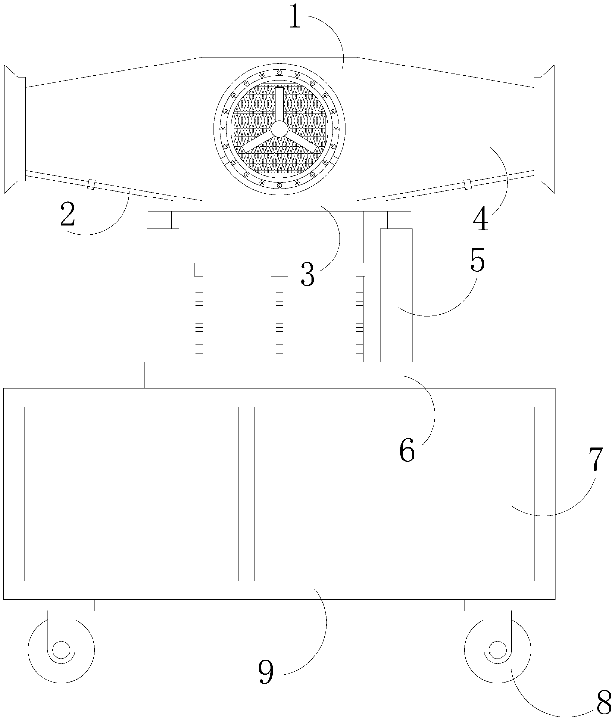
[0034] see figure 1 , the present invention provides a technical solution for road construction dust suppression device: its structure includes a power mechanism 1, a water pipe assembly 2, a fixed support ring 3, an air cylinder 4, a hydraulic cylinder 5, a rotating pan platform 6, a water tank 7, a universal wheel 8, Body 9, universal wheels 8 are installed at the four corners of the bottom of the body 9, a water tank 7 is built in the body 9, the water tank 7 communicates with the water pipe assembly 2, and a rotating pan platform 6 is mounted on the body 9 , the rotating pan platform 6 is connected with the fixed support ring 3 through the hydraulic cylinder 5, and the fixed support ring 3 is fixed on the power mechanism 1, and the four positive directions of the power mechanism 1 are connected with the air cylinder 4, and the Air cylinder 4 is connected with water pipe assembly 2, and the setting of described hydraulic cylinder 5 makes air cylinder 4, power mechanism 1 h...
Embodiment 2
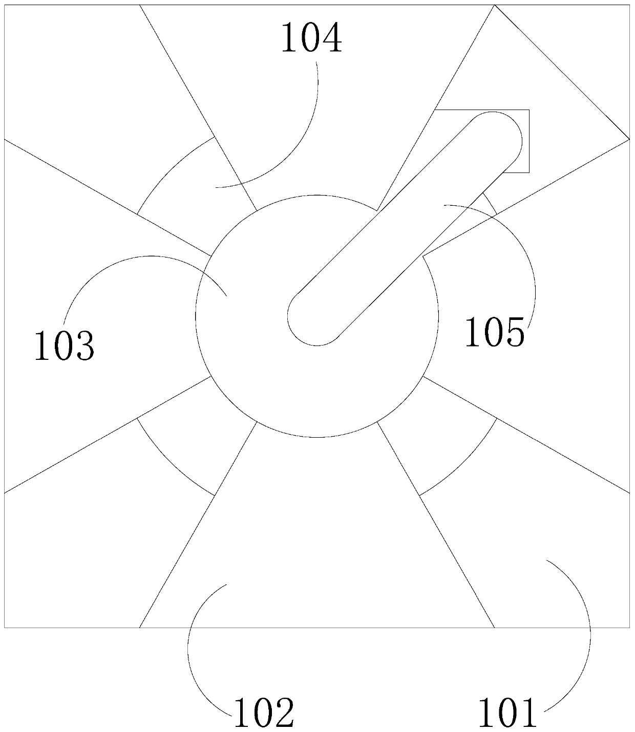
[0041] see Figure 7 , the water pipe assembly 2 includes a water inlet head 201, a water valve 202, an obtuse angle pipe 203, and an L-shaped connecting pipe 204. The quarters of the water inlet head 201 are fixed with an L-shaped connecting pipe 204, and the L-shaped connecting pipe 204 is The obtuse-angle pipes 204 are all connected with obtuse-angle pipes 203, and the obtuse-angle pipes 203 are equipped with water valves 202. The obtuse-angle pipes 203 are connected with the water diffuser ring 405. connection, the obtuse angle pipe 203 runs through the through hole 301 and the round hole 605 that adopt clearance fit with it, the L-shaped connecting pipe 204), the water inlet head 201 is located under the linkage round table 601, the setting of the water valve 202 It can be opened according to the requirements of the dust reduction orientation, so as to select the number of air ducts 4 for spraying and dust reduction. The setting of the L-shaped connecting pipe 204 and the...
PUM
 Abstract
Description
Claims
Application Information