Conveying and guiding structure for PE pipeline production and processing

A guiding structure and pipeline technology, applied in applications, tubular objects, household appliances, etc., can solve the problems of unsmooth rotation of the screw, affecting the production efficiency of the winding pipe, affecting the precision of the pipe forming, etc., and achieves convenient and fast driving and convenient adjustment Fast, jam-proof effect

Active Publication Date: 2020-08-07
SHANDONG ZHONGLU PIPE IND
View PDF6 Cites 0 Cited by
  • Summary
  • Abstract
  • Description
  • Claims
  • Application Information

AI Technical Summary

Problems solved by technology

[0003] However, the traditional guide equipment drives the slider through the screw rod, so that the slider drives two cross-set support rods to rotate, so that the guide wheel is suitable for the production of pipes of different sizes. At the same time, the screw rod is mostly exposed, and the winding pipe cutting process The waste in the guide wheel is easy to fall on the screw, which makes the screw rotate not smooth or even damaged. At the same time, it is not convenient to drive the screw at both ends to rotate at the same time, and the operation efficiency is low. At the same time, when there is too much waste on the guide wheel, it is easy to make the winding tube Vibration when rotating and moving forward, which in turn affects the production efficiency of the winding pipe, affects the forming accuracy of the pipe on the forming machine, and at the same time causes the levelness of the end cutting to be poor when the winding pipe shakes

Method used


Image

  • Conveying and guiding structure for PE pipeline production and processing
  • Conveying and guiding structure for PE pipeline production and processing
  • Conveying and guiding structure for PE pipeline production and processing

Examples


Embodiment Construction

[0026] In order to make the technical means, creative features, goals and effects achieved by the present invention easy to understand, the present invention will be further described below in conjunction with specific embodiments.

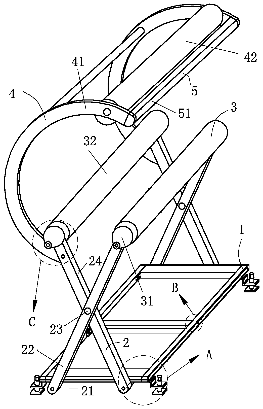
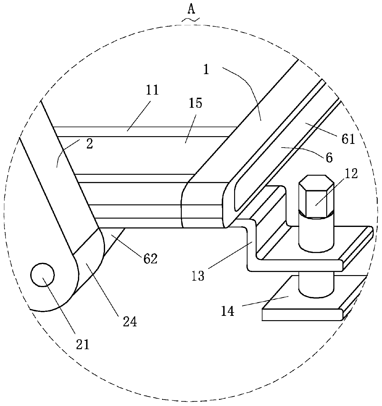
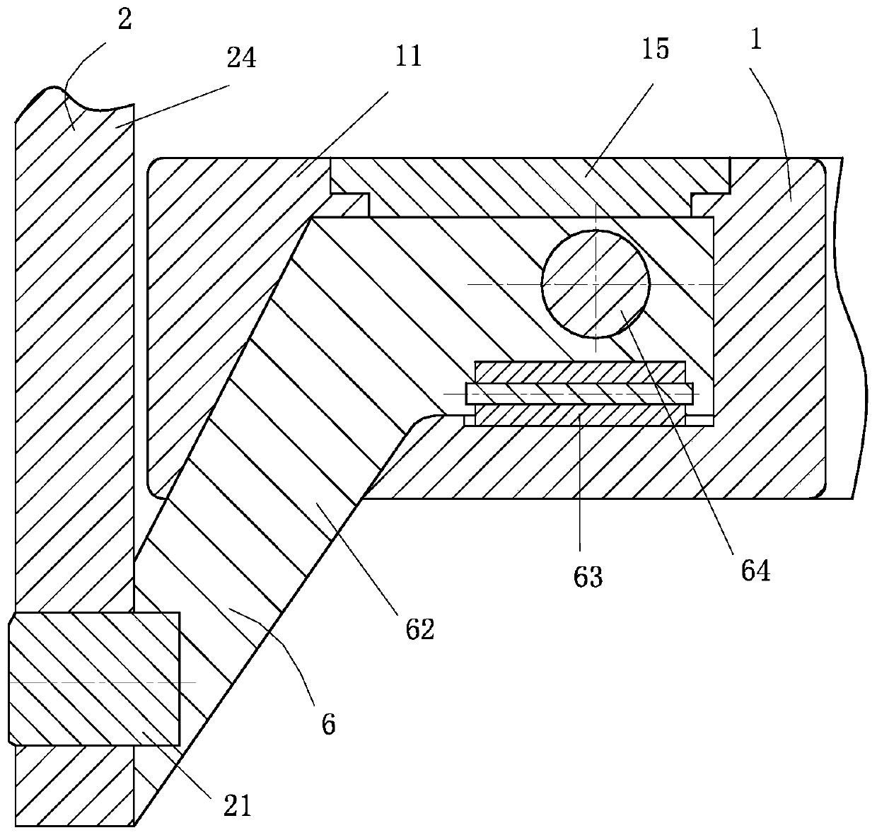
[0027] Such as Figure 1-Figure 8 As shown, a conveying and guiding structure for PE pipeline production and processing according to the present invention includes a supporting structure 1, a transmission structure 2, a guiding structure 3, a limiting structure 4, a cleaning structure 5 and a driving structure 6; it is used to adjust the overall level The supporting structure 1 is provided with the driving structure 6 for simultaneously driving the two transmission structures 2, the driving structure 6 is connected to the transmission structure 2 in rotation, and the transmission structure 2 is connected to the transmission structure 2. The support structures 1 are slidingly connected; the transmission structure 2 is provided with the guide struct...


PUM


Abstract

The invention relates to the field of PE pipeline production and processing devices, in particular to a conveying and guiding structure for PE pipeline production and processing. The conveying and guiding structure comprises a supporting structure, transmission structures, guiding structures, limiting structures, a cleaning structure and driving structures; the limiting structures used for limiting and depressurizing a pipeline are arranged on the transmission structures, then the limiting structures are matched with the guiding structures to limit and guide a PE hollow-wall pipeline from three directions, so that the stability in the pipeline conveying process is greatly improved, the situation that the precision of forming of the pipeline by a forming machine is affected by excessive shaking amplitude of the pipeline is effectively prevented, and the guiding quality of the pipeline is improved; and the cleaning structure used for cleaning sweeps on the pipeline is arranged on the endparts of the limiting structures, the cleaning structure and the two guiding structures are located on three edges of a triangular prism, so that the cleaning structure is in touch with the pipeline,the sweeps on the pipeline are removed, pipeline shaking caused by the sweeps being in touch with the guiding structures is effectively prevented, and thus the forming efficiency and the cutting quality of the pipeline are greatly improved.

Description

technical field [0001] The invention relates to the field of PE pipe production and processing devices, in particular to a conveying guide structure for PE pipe production and processing. Background technique [0002] Polyethylene is a thermoplastic resin obtained by polymerization of ethylene; in industry, it also includes copolymers of ethylene and a small amount of α-olefin; polyethylene is odorless, non-toxic, feels like wax, and has excellent low temperature resistance (minimum The service temperature can reach -100~-70°C), good chemical stability, and can withstand most acid and alkali erosion (not resistant to oxidizing acids), and is used in the production of pipelines, such as PE hollow wall winding pipes, in PE During the production process of the hollow wall winding pipe, since the pipe is rotating, it is necessary to use a guiding device to guide the pipe. [0003] However, the traditional guide equipment drives the slider through the screw rod, so that the slid...

Claims


Application Information

Patent Timeline
Patent Type & Authority Applications(China)
IPC IPC(8): B29C53/80B08B9/023B29L23/00
CPCB08B9/023B29C53/8008B29C53/8091B29L2023/22
Inventor 岳庆民
Owner SHANDONG ZHONGLU PIPE IND
Why Eureka
Try Eureka