Scaffold mounting device

An installation device and scaffolding technology, which is applied in the connection of scaffolding, building structure support, building structure support, etc., can solve the problems of the influence of the space utilization rate of the carriage, the position of the disc cannot be adjusted, and the screw thread is damaged, so as to achieve the convenience of space utilization. The effect of improving installation adjustment ability and ensuring safety

Inactive Publication Date: 2020-08-07
THE FIRST CONSTR ENG COMPANY LTD OF CHINA CONSTR SECOND ENG BUREAU
View PDF12 Cites 0 Cited by
  • Summary
  • Abstract
  • Description
  • Claims
  • Application Information

AI Technical Summary

Problems solved by technology

[0004] The purpose of the embodiments of the present invention is to provide a scaffolding installation device to solve a series of problems caused by the threaded connection of other types of scaffolds and the connection of welding fixtures, such as thread damage and corrosion, and the position of the disc cannot be adjusted. During the transportation process, the space utilization rate of the carriage has a great influence, etc.

Method used


Image

  • Scaffold mounting device
  • Scaffold mounting device
  • Scaffold mounting device

Examples


Embodiment 1

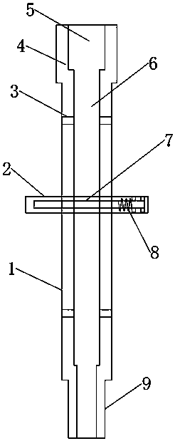
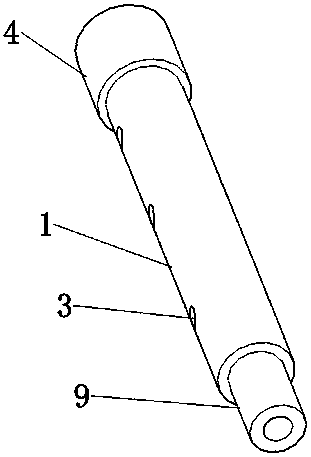
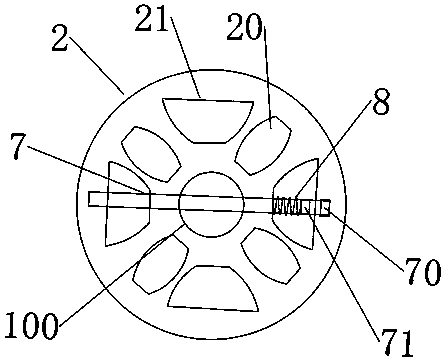
[0027] Such as Figure 1-5 As shown, a scaffolding installation device includes a pole 1 on which a disc 2 is adjustablely mounted, the disc 2 is provided with a mounting hole 100, and the top of the pole 1 is provided with a pier Thick pipe 4, said pier thick pipe 4 is provided with connecting holes 5, said vertical rod 1 is uniformly provided with adjusting holes 3, and the bottom of said vertical rod 1 is provided with a connecting shaft 9, and the outer part of said connecting shaft 9 The diameter is the same as the inner diameter of the connecting hole 5. The disc 2 is evenly provided with a cross-bar mounting hole 20 and a counterbore 21, the cross-bar mounting hole 20 is equipped with a cross-bar, and the inside of the disc 2 is arranged horizontally There is a fixing hole 22 into which a fixing pin 7 is inserted.

[0028] Specifically, the disc 2 is installed through the adjusting hole 3 and the fixing pin 7, and the fixing pin 7 is inserted into the fixing hole 22, whic...

Embodiment 2

[0037] This embodiment is a further improvement and limitation of Embodiment 1 on the basis of Embodiment 1.

[0038] A scaffolding installation device includes all the components in embodiment 1, and also includes:

[0039] The fixed pin 7 is sleeved with a spring 8, the fixed pin 7 is provided with a first pin 70 and a second pin 71, the side of the disc 2 is provided with a horizontal groove 23 and a vertical groove 24, the horizontal The groove 23 and the vertical groove 24 are arranged at ninety degrees. The horizontal groove 23 penetrates the side wall of the counterbore 21, and the vertical groove 24 is embedded in the side wall of the counterbore 21.

[0040] Specifically, in order to ensure the reliability of the installation of the disc 2, after the fixing pin 7 is inserted into the fixing hole 22 of the disc 2, the spring 8 and the first pin 70 and the second pin 71 are used to cooperate with the horizontal groove 23 and the vertical groove 24 in sequence. , To ensure tha...


PUM


Abstract

The invention discloses a scaffold mounting device, and relates to the technical field of scaffold mounting. The problems of mounting, transporting and the like caused by threaded connection and fixedconnection of an existing scaffold are mainly solved. The scaffold mounting device comprises a vertical rod, wherein a disc is adjustably mounted on the vertical rod, and a mounting hole is formed inthe disc; a pier thick pipe is arranged at the top of the vertical rod; a connecting hole is formed in the pier thick pipe; adjusting holes are evenly formed in the vertical rod; cross rod mounting holes and counter bores are evenly formed in the disc, a fixing hole is transversely formed in the disc, and a fixing pin is inserted into the fixing hole; and the fixing pin is sleeved with a spring,a first plug pin and a second plug pin are arranged on the fixing pin, and a transverse groove and a vertical groove are formed in the side face of the disc. Through the structure, the vertical adjusting capacity of a disc buckle type scaffold is improved while the disc buckle type scaffold is quickly mounted and fixed, and thus the scaffold is more convenient to use.

Description

Technical field [0001] The invention relates to the technical field of scaffolding installation, in particular to a scaffolding installation device. Background technique [0002] Scaffolding refers to various supports erected on the construction site for workers to operate and solve vertical and horizontal transportation. A general term in the construction industry, refers to the construction site used for exterior walls, interior decoration, or places with high floors that cannot be directly constructed. Mainly for construction workers to work up and down or to protect the outer safety net and high-altitude installation of components. Scaffolding materials usually include bamboo, wood, steel pipe or synthetic materials. Some projects also use scaffolding as templates. In addition, it is also widely used in the advertising industry, municipal administration, traffic roads and bridges, mining and other departments. For the scaffolding built on the sidewalk or above the road, a sa...

Claims


Application Information

Patent Timeline
Patent Type & Authority Applications(China)
IPC IPC(8): E04G7/22
CPCE04G7/22
Inventor 李卫永徐中强雷丽莉贾斯汉韩明强
Owner THE FIRST CONSTR ENG COMPANY LTD OF CHINA CONSTR SECOND ENG BUREAU
Why Eureka
Try Eureka