Assembled camshaft for engine

A combination and camshaft technology, applied in the direction of engine components, machines/engines, mechanical equipment, etc., can solve the problems of high runout tolerance, affecting the accuracy of parts, non-repeatable assembly, etc., to facilitate mass processing and ensure parts High precision and good remanufacturability

Active Publication Date: 2020-08-07
姬腾飞
View PDF5 Cites 1 Cited by
  • Summary
  • Abstract
  • Description
  • Claims
  • Application Information

AI Technical Summary

Problems solved by technology

The installation and fixing method of the cam unit and the shaft diameter unit on the mandrel is the key to determining the quality of the combined camshaft parts. Among the installation and fixing methods currently used, some use the cam and the shaft diameter unit to press fit through interference fit. Fixed on the mandrel, some use the cam and the shaft diameter unit to heat and expand and then install it on the mandrel, and then fix the cam and the shaft diameter unit on the mandrel after cooling and shrinking, and some use the inner hole of the mandrel to add The pressure makes the mandrel expand, and then fixes it with the cam and the shaft diameter unit. Since the camshaft has high requirements on the angular position of the cam unit, the base circle of each cam, and the runout tolerance of the shaft diameter, the installation of the above-mentioned combined camshaft is fixed. The method has high requirements on the assembly process and tooling equipment, and special equipment is required for assembly. Sometimes after assembly, finishing is required to ensure the accuracy of the parts, which increases the cost and cannot be assembled repeatedly. If a certain cam or shaft is used If the radial unit is damaged, the camshaft needs to be replaced as a whole, which is inconvenient for maintenance and poor in remanufacturability
[0003] Chinese patent application 201710213304.X discloses a segmented camshaft, which divides the camshaft into several sections, and each section is connected to the front section with a connecting flange, which is positioned and fastened by positioning pins and bolts. There is a matching gap between the positioning pin and the pin hole, which will cause the runout deviation of the shaft diameter and the cam of the front section and the rear section, and the positioning accuracy is low, which affects the accuracy of the parts, and because the connecting flange is set on the shaft section, the diameter of the camshaft increases. , the engine needs to have enough layout space, usually only suitable for large engines, poor applicability

Method used


Image

  • Assembled camshaft for engine
  • Assembled camshaft for engine
  • Assembled camshaft for engine

Examples


Embodiment Construction

[0024] The specific technical solutions adopted in the embodiments of the present invention will be described in detail and completely below in conjunction with the accompanying drawings of the present invention. In the description of the present invention, unless otherwise specified, the meaning of "multiple" refers to two or two Above, the orientation or positional relationship indicated by the terms "upper", "lower", "front", "rear", "inner", "outer" and so on are only for the convenience of description and explanation of the present invention based on the appended drawings of the present invention. The orientation or positional relationship shown in the figure should not be interpreted as a specific orientation or positional relationship that the referred devices or components must have, and does not constitute a limitation to the present invention.

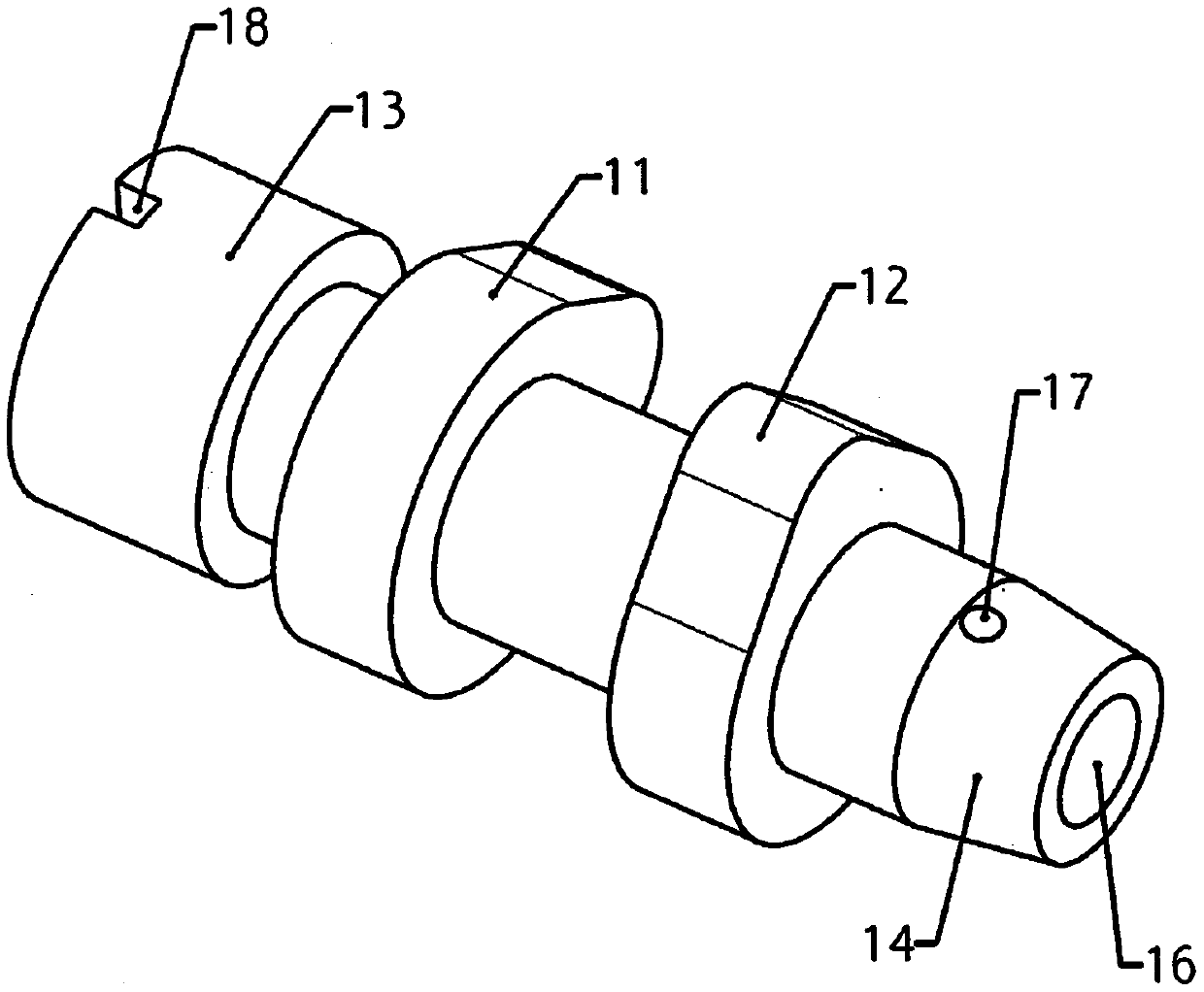
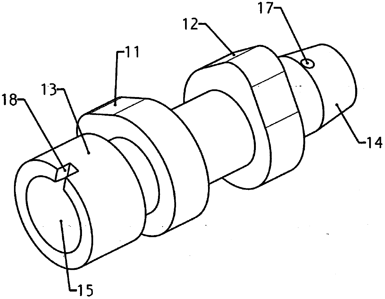
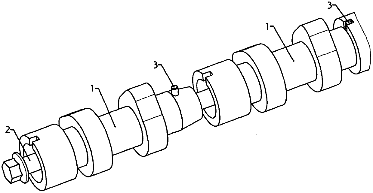
[0025] Figure 1 to Figure 4 The first embodiment of the present invention is described, the combined camshaft is composed ...


PUM


Abstract

The invention provides an assembled camshaft for an engine. The assembled camshaft for the engine is of a segmented structure and is composed of two or more shaft segment units, the front ends and therear ends of the shaft segment units are provided with conical surface shafts and conical surface holes correspondingly, the front ends and the rear ends of the shaft segment units are provided withpositioning pin holes and positioning grooves correspondingly, the shaft segment units are provided with center holes, the assembled camshaft is assembled together by sequentially connecting all the shaft segment units in the front-rear direction, each shaft segment unit is coaxial with the former shaft segment unit through conical surface matching, a phase position of a cam on each shaft segmentis positioned through a corresponding positioning pin and the corresponding positioning groove, and all the shaft segment units are connected and fixed through bolts penetrating through the center holes. The assembled camshaft has the advantages that due to the self-centering effect of conical surface matching, the coaxiality of all the shaft segment units after assembly can be guaranteed, machining is more convenient through the segmented structure, all the shaft segment units have certain universality, special equipment and tool are conveniently adopted for large-batch machining to lower thecost, the camshaft is assembled without the special equipment and tool, all the shaft segment units can be replaced separately, and using and maintenance are convenient.

Description

technical field [0001] The invention relates to a combined camshaft of an engine and belongs to the technical field of engines. Background technique [0002] The camshaft is one of the important parts of the engine. Its main function is to open and close the valve according to the designed time. The camshaft is mainly composed of the shaft diameter part and the intake and exhaust cam parts. At present, the camshaft of the engine is mostly an integral structure , that is, all the shaft diameters of the camshaft and the intake and exhaust cam parts are processed by one shaft segment. For a multi-cylinder engine, the integral camshaft is longer in length, the processing procedure is complicated, and deformation is easy to occur during processing, which affects the accuracy of the parts. Manufacturing The cost is high and the weight is also relatively large. With the development of engine technology, more and more combined camshafts are used. The current combined camshaft is us...

Claims


Application Information

Patent Timeline
Patent Type & Authority Applications(China)
IPC IPC(8): F01L1/047
CPCF01L1/047F01L2001/0473F01L2001/0475
Inventor 姬腾飞
Owner 姬腾飞
Why Eureka
Try Eureka