
Marine micro-surface sampling method

A micro-surface and ocean technology, applied in sampling devices and other directions, can solve the problems of difficult to guarantee the water entry angle and water exit angle, difficult to guarantee the sampling quality, and low degree of automation, so as to achieve real and reliable sampling, ideal sampling thickness, and degree of automation high effect

Active Publication Date: 2020-08-07
QINGDAO NAT LAB FOR MARINE SCI & TECH DEV CENT +1
View PDF8 Cites 2 Cited by
  • Summary
  • Abstract
  • Description
  • Claims
  • Application Information

AI Technical Summary

Problems solved by technology

The drum method is to coat the surface of the roller (diameter 46cm, length 61cm) with a hydrophilic glass fiber coating. The height of the roller contacting the water surface can be adjusted. The motor is connected to the reducer to adjust the speed of the roller. The roller moves slowly in the water to collect a thickness of 50-100μm. The water layer, and finally use the fixed scraper to scrape the water into the sample bottle. The sampling thickness of the rotary drum sampler is ideal, but it cannot work in harsh sea conditions
[0004] Existing patents, such as a Chinese patent with a publication date of 2019.08.23 and a publication number of CN110160840A, disclose a glass plate sampler and its sampling method for collecting micro-surface water samples, but the sampling process requires manual operation, which is complicated and complicated. During the process, the water entry angle, water exit angle and running speed are difficult to guarantee, the stability is poor, the sampling quality is difficult to guarantee, and the degree of automation is low, the sampling efficiency is low, and it is not suitable for working under harsh working conditions.

Method used


Image

  • Marine micro-surface sampling method
  • Marine micro-surface sampling method
  • Marine micro-surface sampling method

Examples


Embodiment Construction

[0047] In the following, the present invention will be specifically described through exemplary embodiments. It should be understood, however, that elements, structures and characteristics of one embodiment may be beneficially incorporated in other embodiments without further recitation.

[0048]In the description of the present invention, it should be noted that the orientation or position indicated by the terms "inner", "outer", "upper", "lower", "front", "back", "left", "right" etc. The relationship is based on the positional relationship shown in the drawings, and is only for the convenience of describing the present invention and simplifying the description, but does not indicate or imply that the referred device or element must have a specific orientation, be constructed and operated in a specific orientation, and therefore cannot be understood To limit the present invention. In addition, the terms "first", "second", and "third" are used for descriptive purposes only, a...


PUM


Abstract

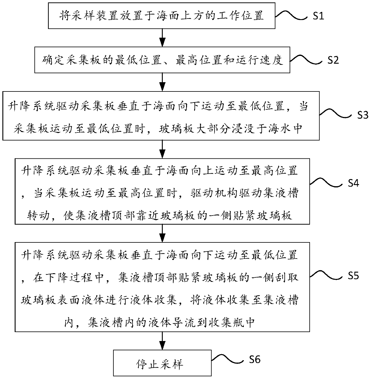
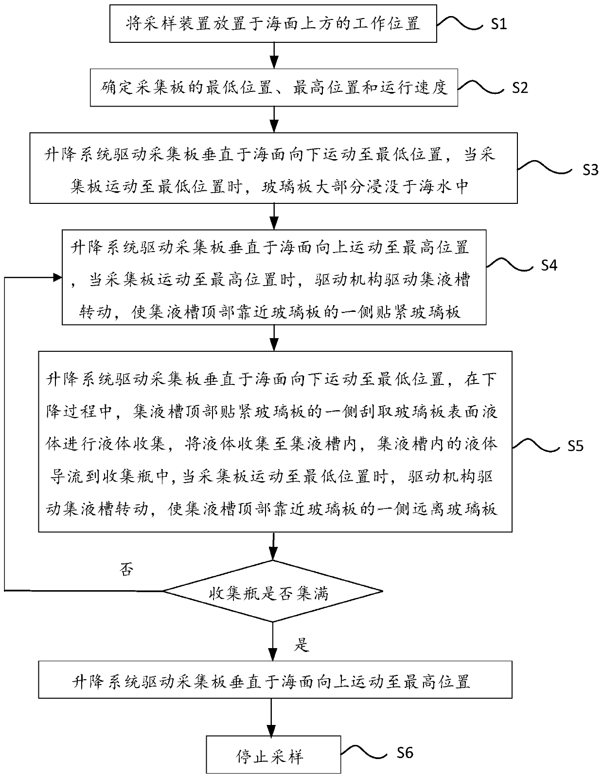
The invention discloses an ocean micro-surface sampling method. The method comprises the following steps that: S1, a sampling device is placed at a working position above the sea surface; step S2, thelowest position, the highest position and the running speed of a collecting plate are determined; S3, a lifting system drives the collecting plate to move downwards to the lowest position perpendicular to the sea surface; S4, the lifting system drives the collecting plate to move upwards to the highest position perpendicular to the sea surface, and when the collecting plate moves to the highest position, a driving mechanism drives a liquid collecting tank to rotate, so that the side, close to a glass plate, of the top of the liquid collecting tank clings to the glass plate; S5, the lifting system drives the collecting plate to move downwards to the lowest position perpendicular to the sea surface, in the descending process, the side, tightly attached to the glass plate, of the top of theliquid collecting tank scrapes liquid on the surface of the glass plate for liquid collection, the liquid is collected into the liquid collecting tank, and the liquid in the liquid collecting tank isguided into a collecting bottle; and S6, sampling is stopped. The sampling method is high in automation degree, high in sampling efficiency, ideal in sampling thickness and capable of meeting the requirements of scientists.

Description

technical field [0001] The invention relates to the technical field of micro-surface sampling, in particular to a marine micro-surface sampling method. Background technique [0002] The ocean microsurface is a thin layer between the atmosphere and the ocean surface, with a thickness of about 30-200 microns. It has unique physical, chemical, and biological characteristics and can enrich various substances. The determination of various parameters in the ocean microsurface is of special significance for the calculation of material flux, climate change prediction, environmental status forecast, and marine biological monitoring. Related research has received long-term attention in the field of marine science. High-quality sampling is a prerequisite for studying the ocean microsurface, and it is also a difficult point in the study of the ocean microsurface. [0003] At present, the sampling methods for the microsurface mainly include the screen method, the glass plate method, and...

Claims


Application Information

Patent Timeline
IPC IPC(8): G01N1/20
CPCG01N1/20
Inventor 李遵伟丁海兵尹航史景文柴瀛张立新
Owner QINGDAO NAT LAB FOR MARINE SCI & TECH DEV CENT
Learn More