Traffic road intersection flow monitoring system

A flow monitoring and flow monitoring technology, applied in traffic control systems, traffic control systems of road vehicles, roads, etc., can solve the problem that signal lights cannot indicate road traffic operation, etc., to achieve convenient and fast maintenance process, convenient maintenance, and reduce traffic accidents. Effect

Inactive Publication Date: 2020-08-11
苏州安泰阿尔法交通科技发展有限公司
View PDF5 Cites 4 Cited by
  • Summary
  • Abstract
  • Description
  • Claims
  • Application Information

AI Technical Summary

Problems solved by technology

[0005] The invention provides a flow monitoring system at traffic road intersections, which solves the technical problem that signal lights need to be manually inspected and repaired through escalators, and the signal lights cannot indicate the operation of road traffic during the repair process.

Method used


Image

  • Traffic road intersection flow monitoring system
  • Traffic road intersection flow monitoring system
  • Traffic road intersection flow monitoring system

Examples


Embodiment 1

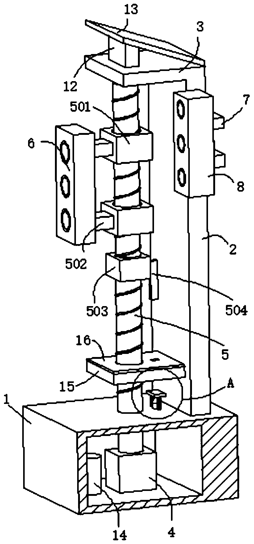
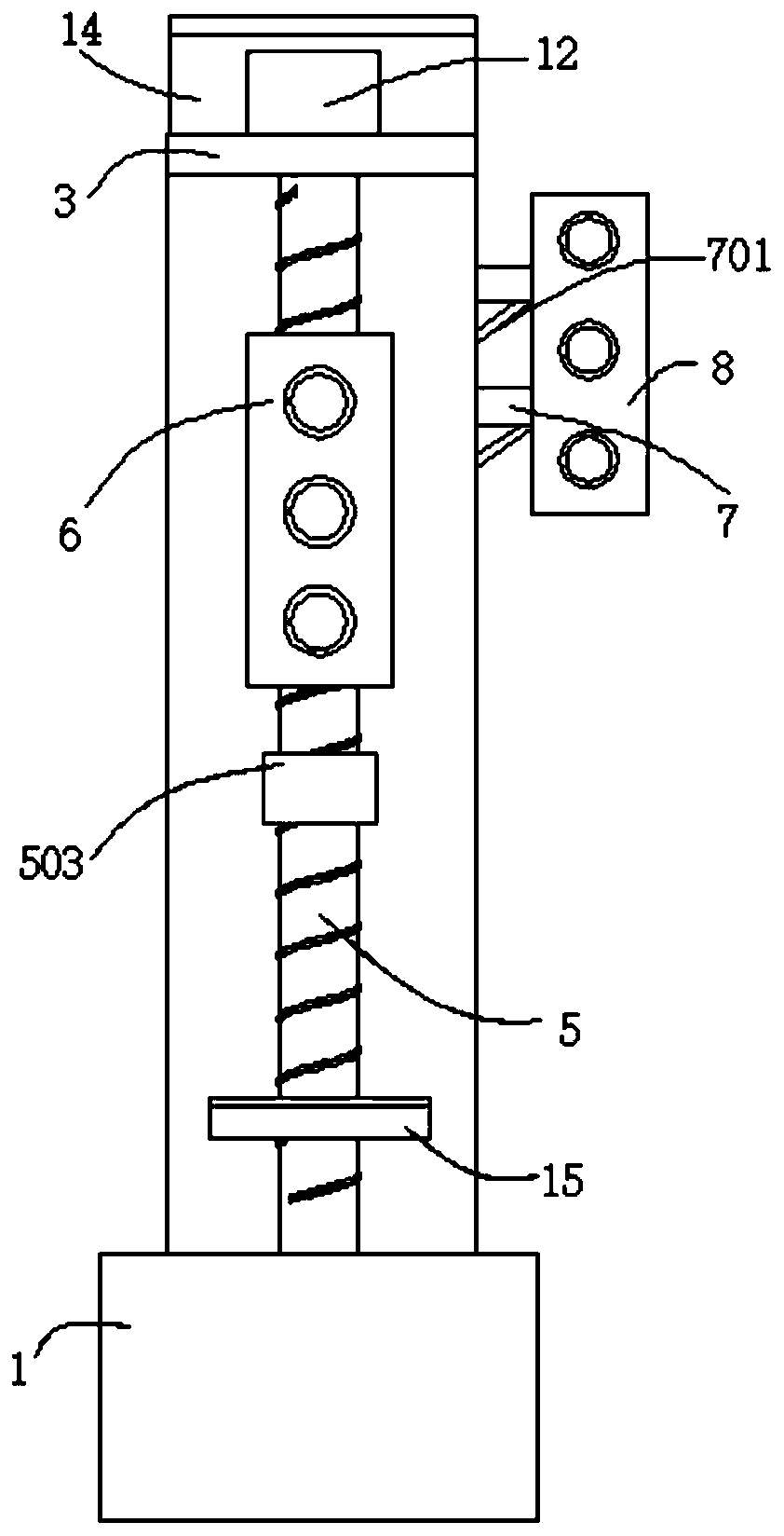
[0027] See Figure 1~3 , The present invention provides a traffic road junction flow monitoring system, including a base 1, a signal lamp system and a flow monitoring system. The top of the base 1 is connected with a vertical plate 2, and the end of the vertical plate 2 away from the base 1 is connected with a top plate 3. The base 1 The inner wall is connected with a motor 4, and the output end of the motor 4 is connected with a rotating shaft. The end of the rotating shaft away from the motor 4 passes through the base 1 and is connected with a screw rod 5. The top of the screw rod 5 is connected to the bottom wall of the top plate 3 through a bearing. 5 The outer wall is threadedly connected with a first sleeve 501, the outer wall of the first sleeve 501 is connected with a connecting rod 502, the end of the connecting rod 502 away from the first sleeve 501 is connected with a first signal lamp 6, and the outer wall of the vertical plate 2 is connected with a supporting rod 7 ...

Embodiment 2

[0030] See Figure 1~4 , The present invention provides a traffic road junction flow monitoring system, including a base 1, a signal lamp system and a flow monitoring system. The top of the base 1 is connected with a vertical plate 2, and the end of the vertical plate 2 away from the base 1 is connected with a top plate 3. The base 1 The inner wall is connected with a motor 4, and the output end of the motor 4 is connected with a rotating shaft. The end of the rotating shaft away from the motor 4 passes through the base 1 and is connected with a screw rod 5. The top of the screw rod 5 is connected to the bottom wall of the top plate 3 through a bearing. 5 The outer wall is threadedly connected with a first sleeve 501, the outer wall of the first sleeve 501 is connected with a connecting rod 502, the end of the connecting rod 502 away from the first sleeve 501 is connected with a first signal lamp 6, and the outer wall of the vertical plate 2 is connected with a supporting rod 7 ...


PUM


Abstract

The invention provides a traffic road intersection flow monitoring system. The traffic road intersection flow monitoring system comprises a base, a signal lamp system and a flow monitoring system, thetop of the base is connected with a vertical plate, a top plate is connected to one end, away from the base, of the vertical plate, a motor is connected to the inner wall of the base, the output endof the motor is connected with a rotating shaft, the end, away from the motor, of the rotating shaft penetrates through the base and is connected with a lead screw, the top of the lead screw is rotationally connected to the bottom wall of the top plate through a bearing, the outer wall of the lead screw is in threaded connection with a first sleeve, and the outer wall of the first sleeve is connected with a connecting rod. The screw rod rotates to make the first sleeve drive a first traffic light to descend for maintenance, so maintenance is convenient; and a second sleeve drives a pressing rod to extrude a switch, the switch controls a second signal light to work, and in the maintenance process of the first signal light, the second signal light indicates road traffic, so normal operationof traffic is facilitated, and traffic accidents are effectively reduced and avoided.

Description

Technical field [0001] The invention relates to the technical field of traffic optimization, in particular to a traffic road junction flow monitoring system. Background technique [0002] Traffic lights are signal lights that direct the operation of traffic, generally composed of red, green, and yellow lights. Red lights indicate no traffic, green lights indicate permission to pass, and yellow lights indicate warnings. Traffic lights are usually divided into: motor vehicle signal lights, non-motor vehicle signal lights , Pedestrian crossing signal lights, direction indicator lights (arrow lights), lane lights, flashing warning lights, road and railway intersection lights. [0003] The existing traffic road signal lights are usually fixed on both sides of the road with a fixed installation height. When the signal lights fail, they need to be manually repaired through the escalator. This not only delays the time for traffic to return to normal, but also is very inconvenient to repair...

Claims


Application Information

Patent Timeline
Patent Type & Authority Applications(China)
IPC IPC(8): E01F9/615E01F9/623G08G1/08G08G1/095H02J7/35F16F15/08
CPCE01F9/615E01F9/623F16F15/08G08G1/08G08G1/095H02J7/35
Inventor 张莉王学佩陈利浩谭奇
Owner 苏州安泰阿尔法交通科技发展有限公司
Why Eureka
Try Eureka